Systems and methods for compressing plasma

a plasma and plasma technology, applied in the field of systems and methods for compressing plasma, can solve the problem that certain implementations may need frequent maintenan

Active Publication Date: 2011-02-03
GENERAL FUSION INC
View PDF102 Cites 67 Cited by
  • Summary
  • Abstract
  • Description
  • Claims
  • Application Information

AI Technical Summary

Benefits of technology

[0011]In some implementations, the plasma can include a fusionable material such as, for example, isotopes of light elements (e.g., deuterium, tritium, helium-3, lithium-6, and/or lithium-7). The higher plasma densities and/or temperatures that are achievable in some such implementations can be sufficien

Problems solved by technology

Whilst certain embodiments of such mechanical compression systems are attractive from, for example, a cost perspective, certain suc

Method used


Image

  • Systems and methods for compressing plasma
  • Systems and methods for compressing plasma
  • Systems and methods for compressing plasma

Examples


Embodiment Construction

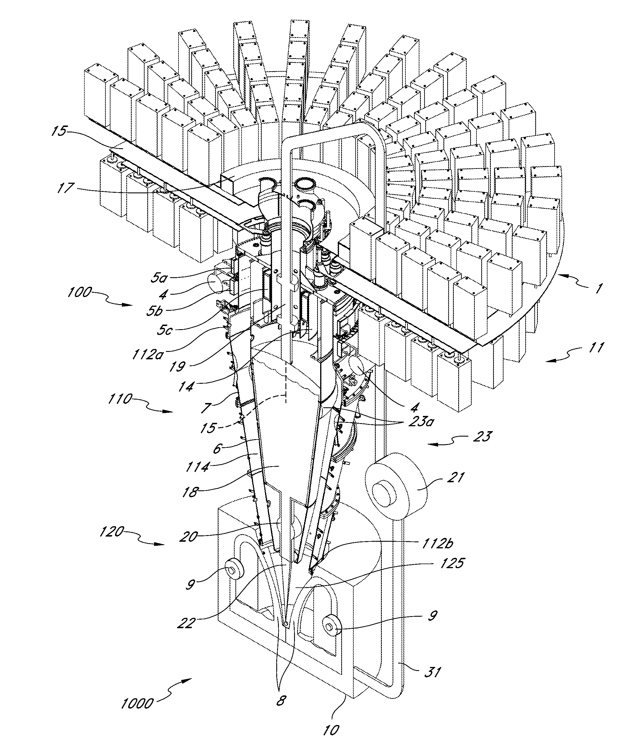
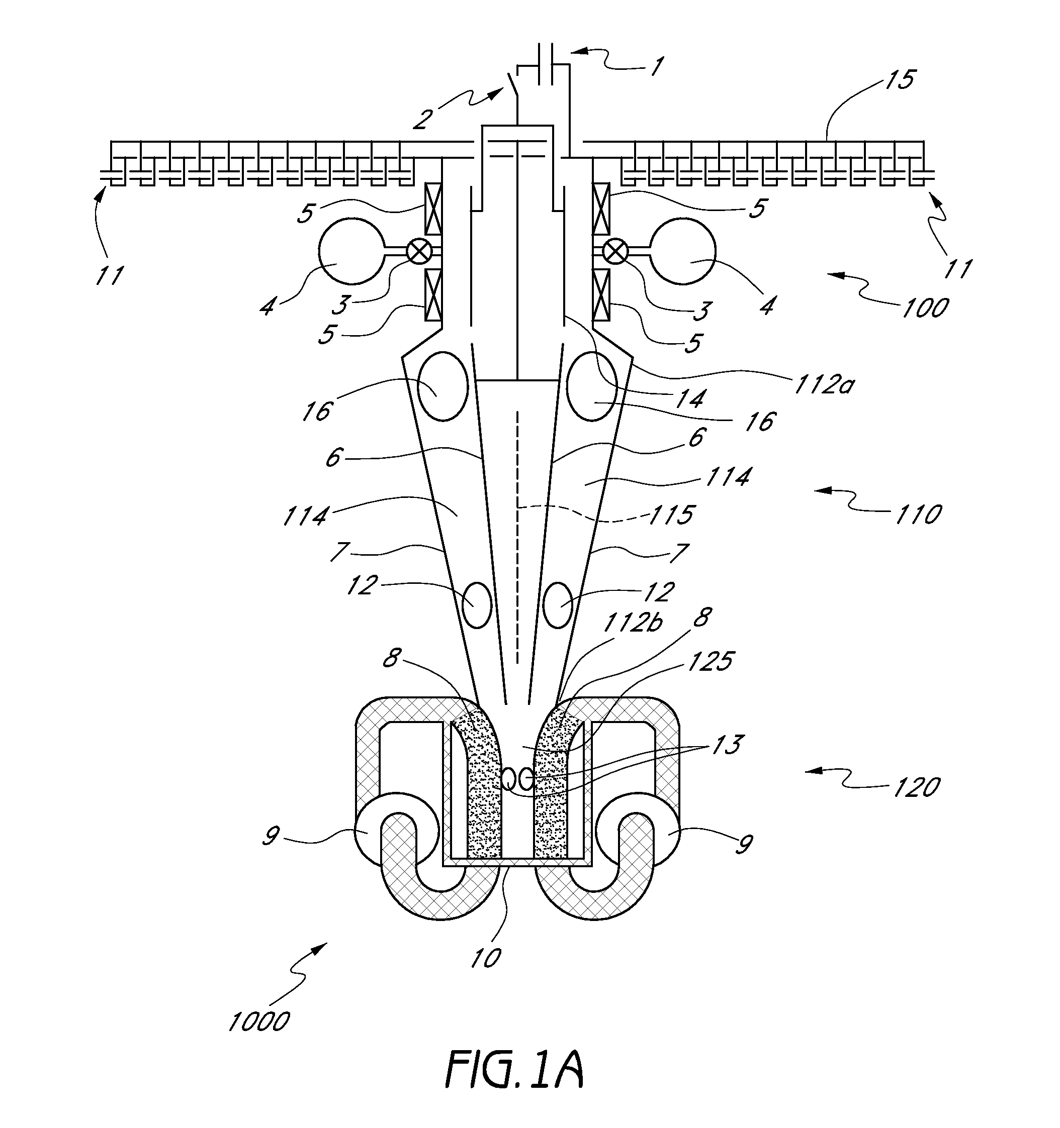
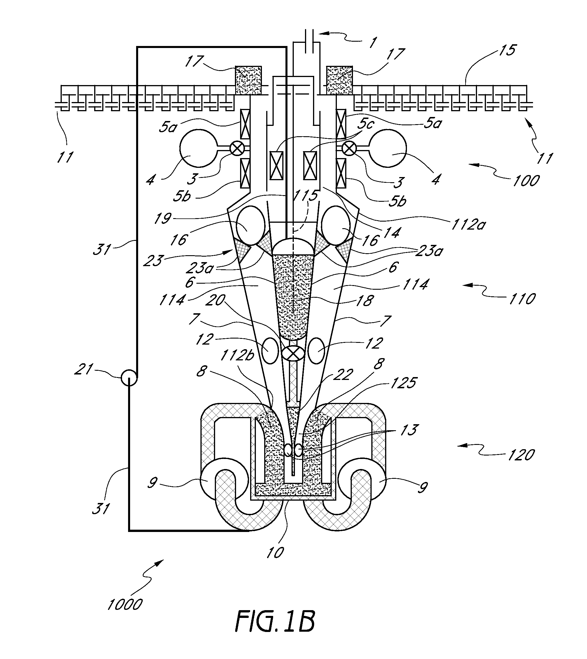
[0022]Tapered coaxial plasma spheromak accelerators have been built and studied in the past for, e.g., x-ray production, tokomak fuelling, and plasma physics research. However, the maximum achievable magnetic pressure has been limited by the strength of the solid materials used in the apparatus (e.g., a fracture limit, yield strength, or breakpoint of the solid materials). In certain embodiments of the present approach, the magnetic pressure that can be achieved has been increased significantly beyond this limit by using a tapered or funnel-shaped liquid metal tube as described in more detail below.

[0023]With reference to the drawings, FIGS. 1A-1D schematically illustrate several embodiments of a system 1000 that can be used to accelerate and compress a plasma. The embodiments shown in FIGS. 1A-1D comprise a plasma gun 100 configured to generate a toroidal plasma (for example, a compact toroid such as, e.g., a spheromak), a plasma accelerator 110 configured to accelerate the plasma ...


PUM


Abstract

Embodiments of systems and methods for compressing plasma are described in which plasma pressures above the breaking point of solid material can be achieved by injecting a plasma into a funnel of liquid metal in which the plasma is compressed and/or heated.

Description

CROSS-REFERENCE TO RELATED APPLICATIONS[0001]This application claims the benefit under 35 U.S.C. §119(e) of U.S. Provisional Patent Application No. 61 / 149,886, filed Feb. 4, 2009, entitled “SYSTEMS AND METHODS FOR ACCELERATING AND COMPRESSING A PLASMA,” which is hereby incorporated by reference herein in its entirety.BACKGROUND[0002]1. Field[0003]The present disclosure relates to embodiments of systems and methods for compressing plasma. In certain such embodiments, a plasma toroid is compressed using a liquid metal funnel.[0004]2. Description of the Related Art[0005]Various systems for heating and compressing plasmas to high temperatures and densities have been described. One approach for accomplishing plasma heating and compression by spherical focusing of a large amplitude acoustic pressure wave in a liquid medium is described in U.S. Patent Publication No. 2006 / 0198486, published Sep. 7, 2006, entitled “Pressure Wave Generator and Controller for Generating a Pressure Wave in a F...

Claims


Application Information

Patent Timeline
IPC IPC(8): G21B1/00
CPCH05H1/16H05H3/06G21B1/057H05H1/54G21B3/008Y02E30/10
Inventor LABERGE, MICHEL GEORGESRICHARDSON, DOUGLAS H.
Owner GENERAL FUSION INC
Why Eureka
Try Eureka