
Method and Apparatus for Capturing Wind to Produce Electrical Power

a technology of wind and electric power, applied in the direction of wind motors with perpendicular air flow, liquid fuel engine components, non-positive displacement fluid engines, etc., can solve the problems of electric harvesting dropping enormously and possibly to zero, blades flying off the pole, and propeller-type units having to face into the wind, so as to increase the ability to move the leading face, reduce drag, and increase surface area

Active Publication Date: 2011-02-03
THE CORRADO FAMILY PARTNERSHIP
View PDF12 Cites 18 Cited by
  • Summary
  • Abstract
  • Description
  • Claims
  • Application Information

AI Technical Summary

Benefits of technology

[0012]The invention offers a horizontal design which has traditional horizontal advantages but in addition offers a massive surface area which can be created while at the same time reducing drag by a rotatable flap system which is rotatably supported on horizontal blade arms. The invention increases the ability to move the leading face of a flap, namely, the windblown face and by decreasing the wind resistance of the trailing face of the flap.
[0013]One can improve rotational speed by increasing the “pushed” surface or decrease the “trailing” surface (drag). The invention does both at the same time using an aerodynamic approach that is positive and unique to wind turbines.
[0014]The trailing blade moving into the wind undergoes passive conformational positioning leading to optimized aerodynamics in a partially reduced angle of the blade thereby decreasing drag. In similar fashion, as this blade rotates into the position pushed by the wind, the passive process produces an increased angle configuration leading to maximized surface access to the wind and therefore increased wind harvest.
[0016]The method and system use arms with flaps which enable a single turbine system to yield enormous amounts of electricity even in a relatively low wind environment. The blade arms are constructed with a male-female system in which the blade arms with flaps open passively in the leading positions and close passively in the wind trailing position so as to maximize wind harvest and reduce wind drag. A rotor shaft drives a turbine located potentially in a number of various locations including the base either as a single generator or as a series of generators. As a consequence of constructed size and passive flap opening action a single such constructed wind turbine can increase the surface area enormously and yield electricity from four to forty fold more than the current largest wind turbines. When used in an off shore setting these turbines are anchored at sea bed by a series of underwater construction which also serve as an artificial reef to improve marine habitants and echo systems.
[0025]I provide a method for capturing wind forces to rotate a rotor shaft of a wind turbine to produce electrical power in which I provide a substantially vertical rotor shaft having a bottom end that is rotatably coupled to an anchor pad; a substantially horizontal blade arm that is joined to the rotor shaft that vertically supports the blade arm. I provide a blade assembly that is coupled to the blade arm and has a rotatable flap, the flap having a leading face and an opposite trailing face so that when the flap is in an open position the wind engages the leading face and pushes against the leading face causing the face to move with the wind and rotate the rotor shaft in a certain direction. As the rotor rotates, the blade arm and blade assembly move to a position where the wind pushes against the trailing face of the flaps. This causes the flap to go to a closed position that reduces drag on the blade arm.
[0027]I provide a rotatable flap and a cooperating flap coupled to the blade assembly in which the flap and cooperating flap have leading faces and opposite trailing faces. The leading faces of the flap and cooperating flap form an open position when the flap is in an open position. The open position formed by the flap and the cooperating flap captures wind pushing against the leading faces of the flap and cooperating flap. When the wind contacts the trailing faces of the flap and the cooperating flap, the open position formed by the flap and the cooperating flap is collapsed by the wind causing the leading face of the flap and the leading face of the cooperating flap to close toward each other thereby reducing drag on the blade arm.

Problems solved by technology

There are two fundamental problems with the propeller design.
First, the propeller design has a natural tendency to “fly” in a direct line just as a plane would fly.
Winds above this, however, could cause the blades to fly off the pole.
The second problem with the current propeller design is that such propeller-type units must face into the wind.
If the unit fails to rotate into the wind the electrical harvest will drop enormously and possibly to zero.
Finally, while not an issue of generation, the propeller designs kill migratory birds.
Horizontal units, however, have their own problems.
The first problem is that the horizontal units are top heavy.
For this reason they are very small and most suited for homes and office units but not for the primary energy of electrical energy grid.
A second problem is inefficiency due to drag.
While this does allow directional movement there is drag and inefficiency which still remains significant.

Method used


Image

  • Method and Apparatus for Capturing Wind to Produce Electrical Power
  • Method and Apparatus for Capturing Wind to Produce Electrical Power
  • Method and Apparatus for Capturing Wind to Produce Electrical Power

Examples


Embodiment Construction

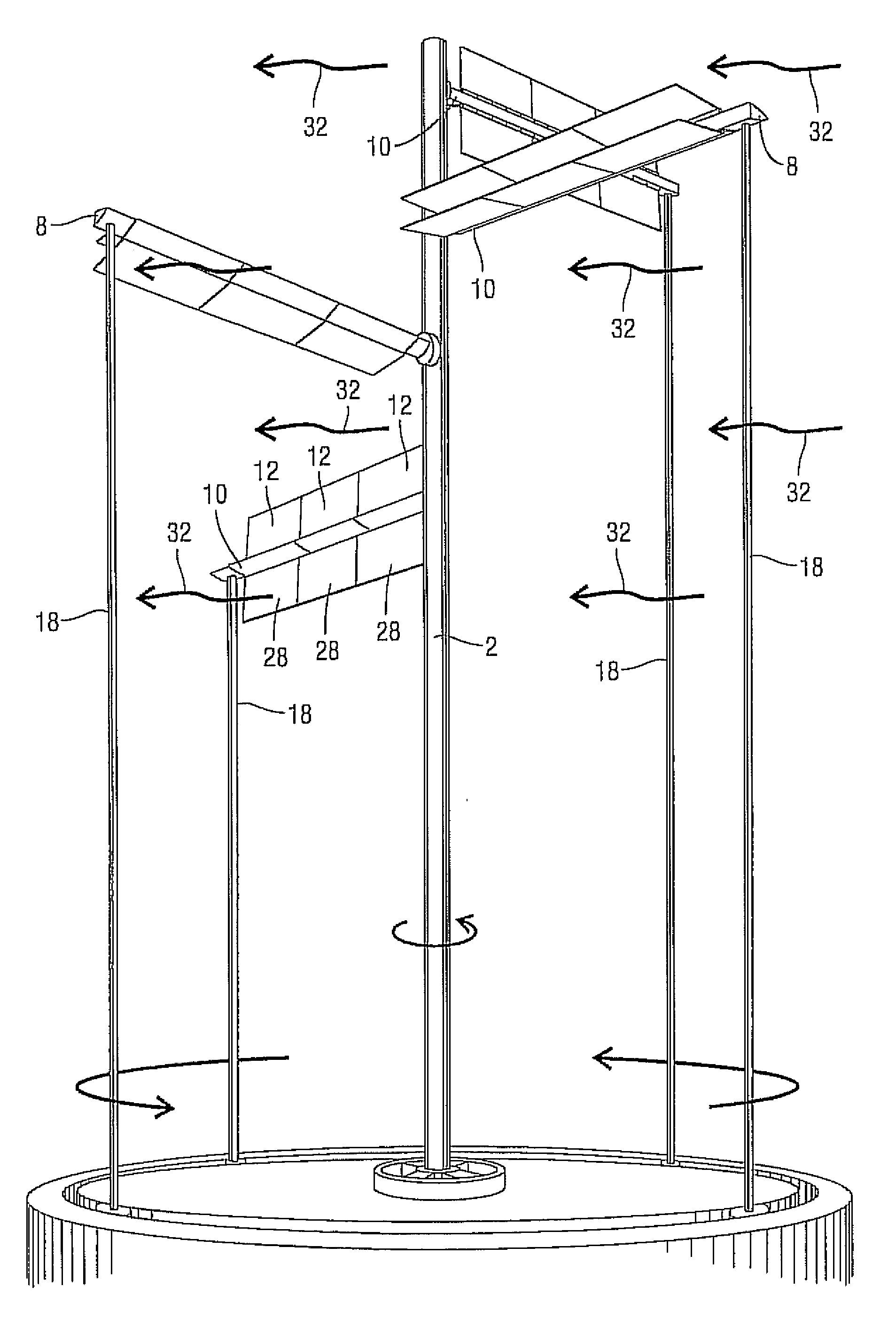
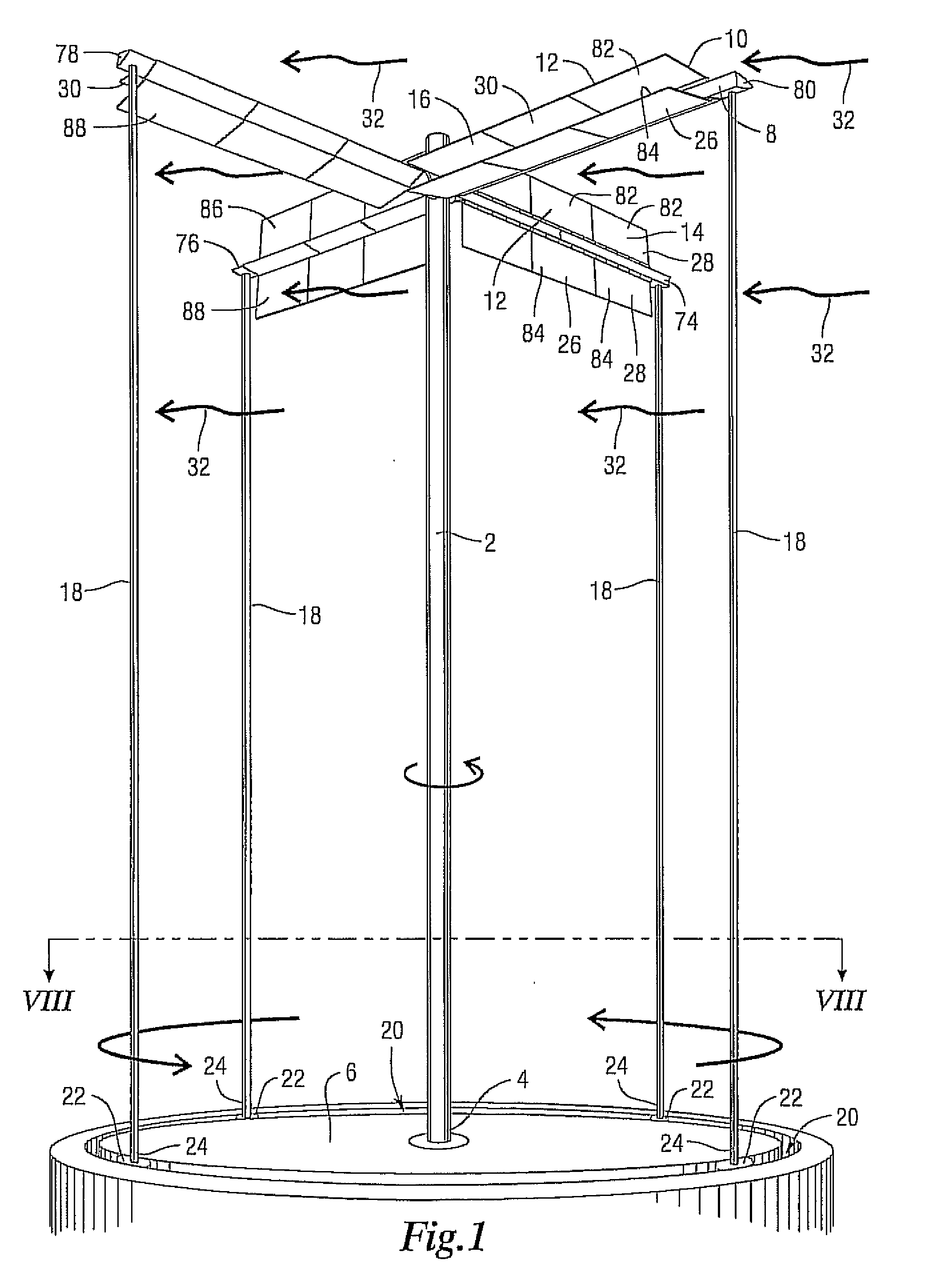
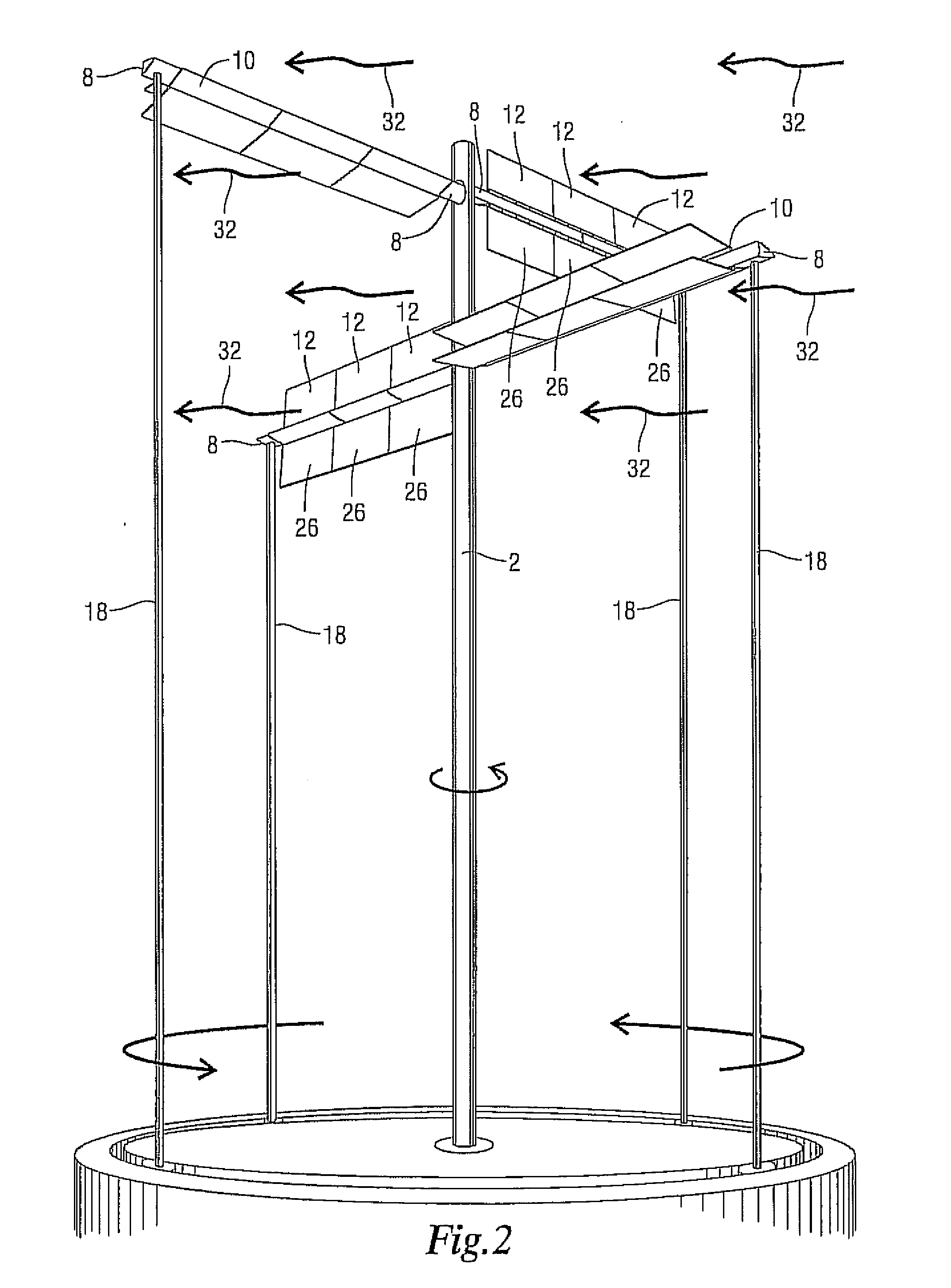
[0041]FIG. 1 shows a blade system for use in a wind turbine to produce electrical power. A substantially vertical rotor shaft 2 having a rotor shaft bottom 4 is rotatably coupled to anchor pad 6 at the rotor shaft bottom 4. A substantially horizontal blade arm 8 is supported by the rotor shaft 2. A blade assembly 10 has a rotatable flap 12 capable of opening and closing to provide an open position 14 and a closed position 16 and is rotatably coupled to the blade assembly 10. A support pole 18 is coupled to the blade arm 8 and vertically supports the blade arm 8. A track 20 surrounds the rotor shaft 2. A track device 22 is movably coupled to the track 20. A bottom end 24 of the support pole 18 is coupled to the track device 22. The bottom end 24 of support pole 18 is spaced radially from the rotor shaft 2.

[0042]A rotatable cooperating flap 26 is rotatably coupled to the blade assembly 10. The flap 12 and the cooperating flap 26 form an open position 28 when the flap 12 is in the open...


PUM


Abstract

A blade system and method of use for a wind turbine to produce electrical power. The system has a vertical rotor shaft coupled to an anchor pad and supports a horizontal blade arm. A blade assembly having a rotatable flap is coupled to the blade arm. The flap captures the wind which causes the rotor shaft to rotate and generates electrical power from an electrical generator.

Description

CROSS-REFERENCE TO RELATED APPLICATIONS[0001]None.STATEMENT REGARDING FEDERALLY SPONSORED RESEARCH OR DEVELOPMENT[0002]Not ApplicableTHE NAMES OF THE PARTIES TO A JOINT RESEARCH AGREEMENT[0003]Not ApplicableBACKGROUND OF THE INVENTION[0004]1. Field of the Invention[0005]The present invention is related to a blade system for use in a wind turbine in which the wind rotates a rotor shaft to a generator that produces electrical energy. The blade system has a blade arm with blade assemblies that have rotatable flaps.[0006]2. Description of Related Art[0007]The amount of kinetic energy that can be harvested for the production of electricity is a function of wind velocity, surface area and efficiency of the blade system. The current propeller-type wind turbines harvest most of the wind energy today. The blades are 35 meters in length and currently newer turbines will use blades of 42 meters in length. There are two fundamental problems with the propeller design.[0008]First, the propeller d...

Claims


Application Information

Patent Timeline
Patent Type & Authority Applications(United States)
IPC IPC(8): F03D3/06F03D11/00F03D9/00
CPCF03D3/067Y02E10/74F05B2240/218
Inventor CORRADO, MICHAEL L.
Owner THE CORRADO FAMILY PARTNERSHIP
Features
  • Generate Ideas
  • Intellectual Property
  • Life Sciences
  • Materials
  • Tech Scout
  • Unparalleled Data Quality
  • Higher Quality Content
  • 60% Fewer Hallucinations
Learn More