
Biochemical reaction cassette

a biochemical reaction and cassette technology, applied in the direction of flow control, process and machine control, instruments, etc., can solve the problems of no labeled target nucleic acid generation, complicated overall operation, and long diagnosis tim

Inactive Publication Date: 2011-02-03
CANON KK
View PDF13 Cites 4 Cited by
  • Summary
  • Abstract
  • Description
  • Claims
  • Application Information

AI Technical Summary

Benefits of technology

[0012]It is an object of the present invention to provide a biochemical reaction cassette having a structure for uniformizing a liquid flow in a reaction chamber with a simple additional arrangement.
[0013]A biochemical reaction cassette for detecting a target substance according to a first aspect of the present invention includes a reaction chamber for bringing a sample into contact with a probe-immobilizing region for detecting a target substance; an injection port for injecting the sample into the reaction chamber; a discharge port for discharging the sample from the reaction chamber; and a fluid resistive section disposed in a channel that is constructed to includes the injection port, the reaction chamber, and the discharge port. The fluid resistive section reduces the cross-sectional area of the channel and has a structure that gives a difference in the fluid resistance in the portion where the fluid resistive section is disposed in such a manner that the fluid resistance at least one end in the width direction of the channel is lower than those in the other portions.
[0016]According to the present invention, the fluid flow can be uniformly controlled by arranging a fluid resistive section in a channel constructed to include the injection port, the reaction chamber, and the discharge port so as that the cross-sectional area of the channel is reduced. However, the flow rate is decreased at the ends in the width direction of the fluid resistive section and in portions remote from the injection port and the discharge port. Accordingly, the flow resistance is reduced for preventing the decrease in the flow rate. The flow rate can be readily controlled to be uniform by arranging the injection port and the discharge port in the central portion in the channel width direction and by decreasing fluid resistance at both ends in the channel width direction by approximately the same degrees lower than that in the central portion. In addition, the flow rate in the reaction chamber can be uniformized by preventing a decrease in the flow rate at both ends of the reaction chamber by regulating the structure of the reaction chamber so that the fluid resistance near both ends, where the flow rate is low, in the width direction of the reaction chamber is smaller than that in the central portion. The further uniform flow rate can be achieved by simultaneously adopting such a structure of the reaction chamber and the above arrangement of the fluid resistive section.

Problems solved by technology

However, when the nucleic acid sample solution does not contain the target nucleic acid, no labeled target nucleic acid is generated.
Consequently, the overall operation is complicated, and diagnosis hence takes a long time.
Accordingly, the probe may be lost or contaminated by touching the slide glass with a finger or the like.

Method used


Image

  • Biochemical reaction cassette
  • Biochemical reaction cassette
  • Biochemical reaction cassette

Examples


first embodiment

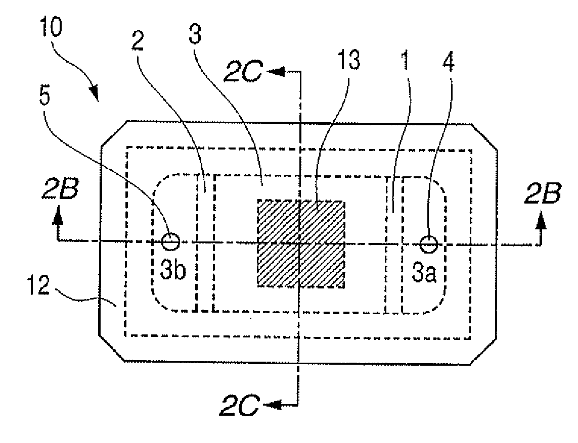
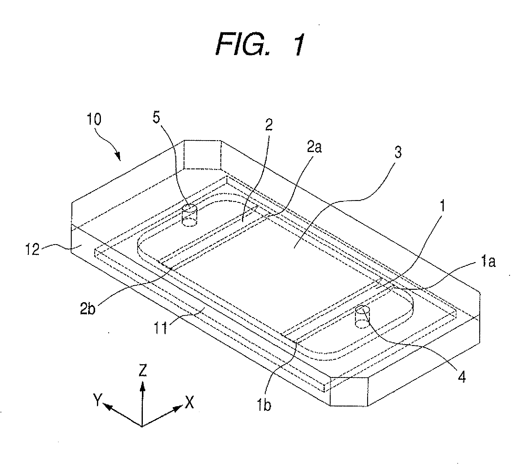
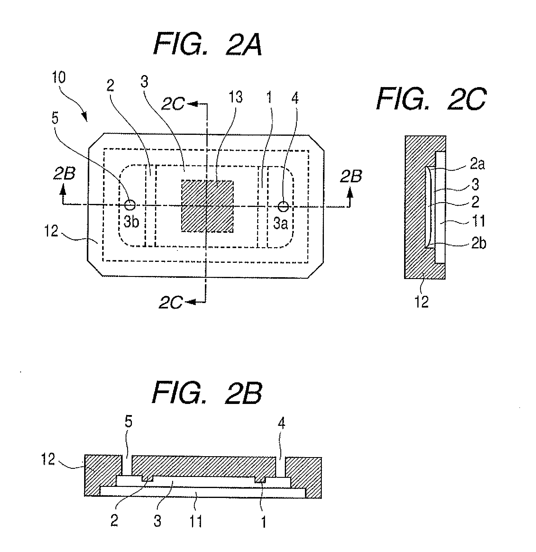
[0031]FIG. 1 is a perspective view illustrating the structure of a biochemical reaction cassette according to a first embodiment of the present invention. FIG. 2A is a plan view and FIGS. 2B and 2C are cross section views illustrating the structure of the biochemical reaction cassette according to the first embodiment of the present invention. FIG. 2B is a cross section view taken along the section 2B-2B of FIG. 2A, and FIG. 2C is a cross section view taken along the section 2C-2C.

[0032]Firstly, the structure of the cassette will be described. The cassette 10 includes a glass substrate 11 and a casing 12 that are bonded to each other. The casing is made of polycarbonate and may be formed into various shapes for bonding to the glass substrate, including the illustrated one. The material of the casing 12 is not limited to polycarbonate and may be, for example, plastic other than polycarbonate, glass, rubber, silicone, or a composite of at least two of these materials. The casing 12 is...

second embodiment

[0051]FIG. 3 is a perspective view illustrating the structure of a biochemical reaction cassette according to a second embodiment of the present invention. FIG. 4A is a plan view and FIGS. 4B and 4C are cross section views illustrating the structure of the biochemical reaction cassette according to the second embodiment of the present invention. FIG. 4B is a cross section view taken along the section 4B-4B of FIG. 4A, and FIG. 4C is a cross section view taken along the section 4C-4C.

[0052]The structure of the cassette 10 has a structure in which pillar-shaped members 21 and 22 are employed instead of the protrusion members 1 and 2 in the first embodiment. A solution passes through gaps formed by the pillar-shaped members 21 and gaps formed by the pillar-shaped members 22. The gaps formed by the pillar-shaped members 21 are large at both ends 21a and 21b thereof. Similarly, the gaps formed by the pillar-shaped members 22 are broad at both ends 22a and 22b thereof. In this example, ea...

third embodiment

[0055]FIG. 5 is a perspective view illustrating the structure of a biochemical reaction cassette according to a third embodiment of the present invention. FIG. 6A is a plan view and FIGS. 6B and 6C are cross section views illustrating the structure of the biochemical reaction cassette according to the third embodiment of the present invention. FIG. 6B is a cross section view taken along the section 6B-6B of FIG. 6A, and FIG. 6C is a cross section view taken along the section 6C-6C.

[0056]The structure of the cassette 10 has a structure in which bulkhead members 31 and 32 are employed instead of the protrusion members 1 and 2 respectively in the first embodiment. The bulkhead members 31 and 32 are provided with a large number of through holes for passing a liquid in the Y-direction shown in FIG. 5. Small gaps are provided in both ends 31a and 31b of the bulkhead member 31 and in both ends 32a and 32b of the bulkhead member 32 to reduce fluid resistance. This example describes a struct...


PUM

PropertyMeasurementUnit
cross-sectional areaaaaaaaaaaa
resistanceaaaaaaaaaa
fluid resistanceaaaaaaaaaa

Abstract

A biochemical reaction cassette having a structure for uniformizing a liquid flow in a reaction chamber with a simple additional arrangement is provided. A fluid resistive section is arranged in a channel that is constructed to include an injection port, a reaction chamber, and a discharge port. The fluid resistive section decreases the cross-sectional area of the channel to decrease the fluid resistance at ends in the width direction of the fluid resistive section and at positions remote from the injection port and the discharge port, where the flow rate is decreased.

Description

TECHNICAL FIELD[0001]The present invention relates to a biochemical reaction cassette including a probe carrier such as a DNA microarray. The biochemical reaction cassette can be suitably used for examining a sample such as blood for, for example, whether a gene derived from a pathogenic microorganism is present or not and the result can be used as one factor in the determination of the subject's health condition. More specifically, the present invention relates to a structure of the biochemical reaction cassette for improving a flow of a liquid or a gas present in a reaction chamber.BACKGROUND ART[0002]Many methods utilizing a hybridization reaction using a probe carrier typified by a DNA microarray have been proposed as methods for rapidly and precisely determining the base sequence of a nucleic acid or detecting a target nucleic acid in a nucleic acid sample. The DNA microarray is that in which a probe including a nucleotide sequence that is complementary to a target nucleic acid...

Claims


Application Information

Patent Timeline
Patent Type & Authority Applications(United States)
IPC IPC(8): C40B60/12
CPCG01N33/5302G01N21/00G05D7/00G01N33/54366
Inventor AOYAGI, TAKAAKIMAKIHIRA, TOMOYUKI
Owner CANON KK
Learn More