Soil contamination detector and detection method

Inactive Publication Date: 2011-02-10
LAND ECO CORP
View PDF1 Cites 6 Cited by
  • Summary
  • Abstract
  • Description
  • Claims
  • Application Information

AI Technical Summary

Benefits of technology

[0022]According to the present invention, which comprises the above-described features, because it is configured such that contamination is determined by using a sensor disposed in a region under contamination investigation, and comparing a concentration of a contaminant detected by the sensor with a tolerance limit concentration of the contaminant (claims 1 and 3), soil contamination can be determined simply by having a structure for transmitting an output from the sensor to the control mechanism.
[0023]According to the present invention having such a structure, soil contamination can be determined far more easily than the case where samples are drilled, transported to an analysis facility, and subjected to gas chromatography analysis at the analysis facility. Further, cost reduction can be achieved by eliminating the necessity for collecting samples, transporting them, and processing them in a special-purpose facility.
[0024]Because studies of the inventors have indicated that it is possible to identify all odors of contaminants currently known as causes of soil contamination problems, detection of an odor makes it possible to very precisely detect a contaminant. In addition, because it is also possible to d

Problems solved by technology

Soil that is contaminated by hazardous substances may adversely affect the health of residents, and is therefore unsuitable as a place of residence and also undesirable for raising animals or growing plants.
For the above-described reasons, or due to various other factors, the fact that the soil is contaminated by hazardous substances constitutes a factor (a defect factor) that reduces the collateral value as real estate.
However, such a conventional method requires very cumbersome work, such as boring the soil to be investigated, collecting sample lots at various depths, transporting the collected sample lots to an investigation institutio

Method used


Image

  • Soil contamination detector and detection method
  • Soil contamination detector and detection method
  • Soil contamination detector and detection method

Examples


first embodiment

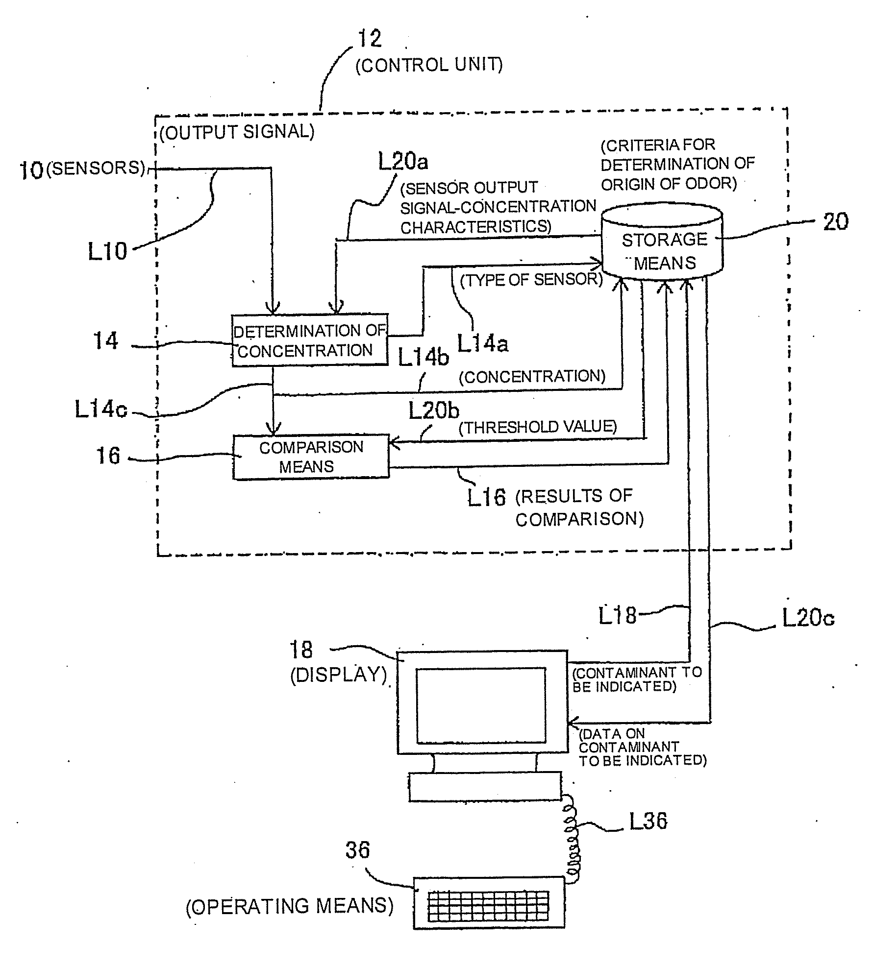
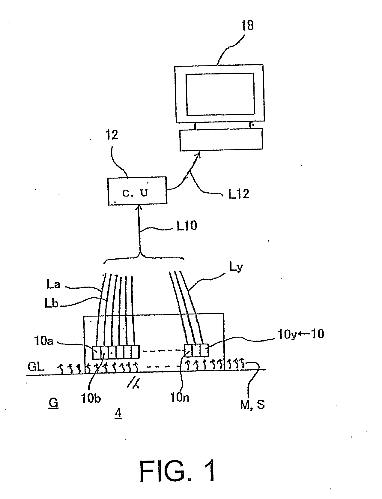
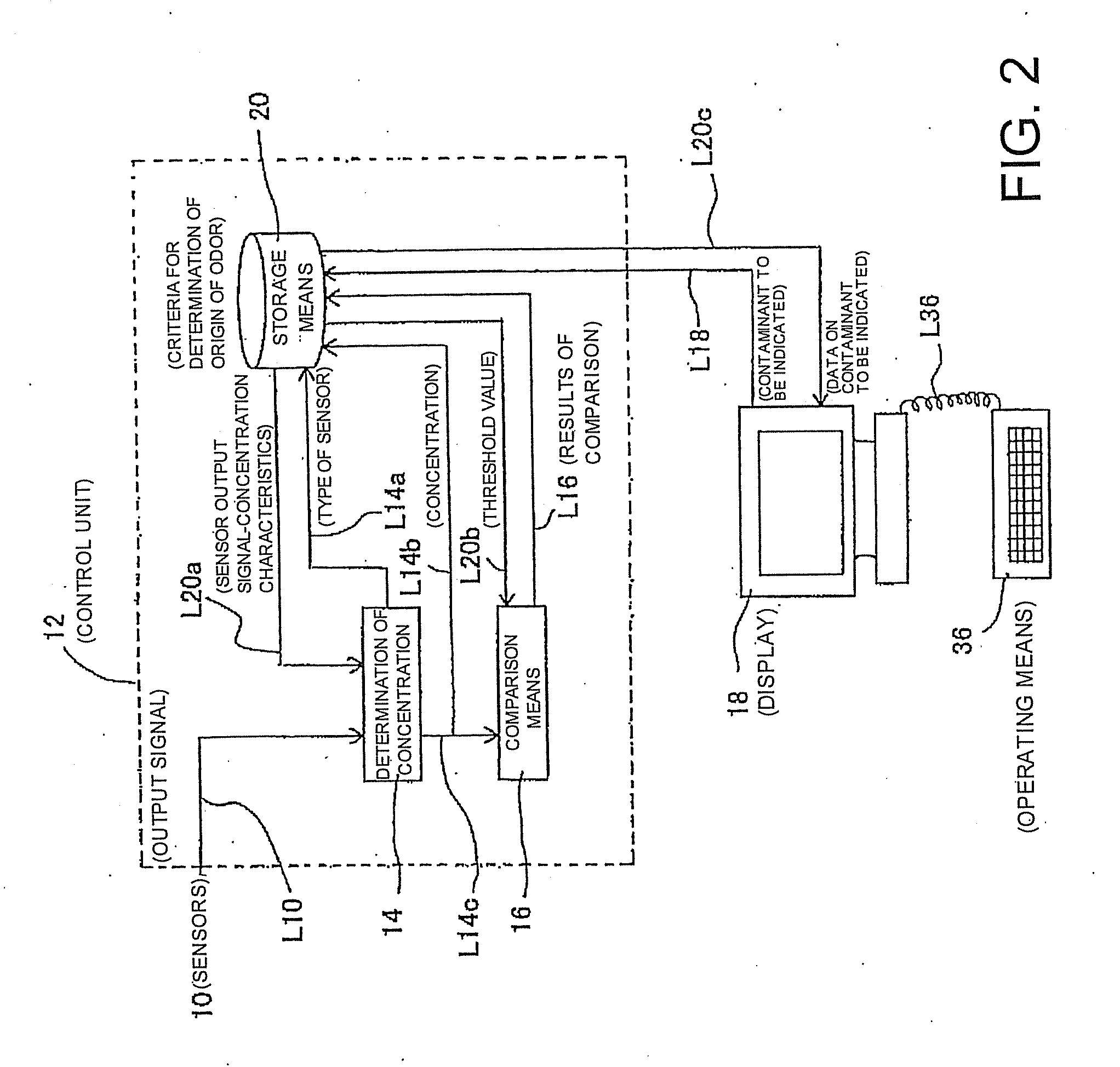
[0028]FIGS. 1 through 3 illustrate the present invention.

[0029]Referring to FIG. 1, which illustrates an overall structure, a plurality of thin film sensors 10a, 10b . . . 10y (hereinafter, collectively referred to as 10) are provided, in a number corresponding to the number of types of contaminants to be detected, over a ground level GL of a ground G within a region 4 under contamination investigation in order to analyze odors S wafting up from the ground level GL, and the plurality of sensors 10 are connected through a signal line L10 to a control mechanism 12, which will be described in detail later. Here, the signal line L10 is formed by binding signal lines La, Lb . . . Ly for communicating detection data transmitted from each of the sensors 10.

[0030]The sensors 10 can detect the presence or absence of a contaminant, and can also detect its concentration D.

[0031]When the thin film sensors described above are used, if the concentration D of a contaminant to be detected is higher...

second embodiment

[0065]FIGS. 5 through 11 illustrate a

[0066]The ground in Japan is mostly composed by layering a plurality of different types of layers, and also in connection with soil contamination it can be expected that the conditions of contamination may differ at different depths.

[0067]In such situations, in the first embodiment shown in FIGS. 1 through 4, the conditions of contamination varying at different depths of the ground G cannot be ascertained.

[0068]According to the second embodiment illustrated in FIGS. 5 through 11, the state of contamination is investigated by detecting odors S from the ground G for each predetermined depth, and therefore this embodiment has an advantage in that the conditions of contamination varying at different depths can be ascertained.

[0069]FIG. 5 illustrates a step of drilling a borehole 6 into the ground G which is to be under contamination investigation. There is shown a state in which the borehole 6 is drilled to a predetermined depth using a boring rod 30...

third embodiment

[0099]FIGS. 12 through 17 illustrate the present invention.

[0100]The third embodiment is an embodiment which combines the first embodiment and the second embodiment. The third embodiment will also be described with reference to FIGS. 1 and 2 of the first embodiment as the overall structure and the control mechanism are generally similar to those described in the first embodiment.

[0101]In the third embodiment, first, as shown in FIG. 12, a plurality of boreholes are drilled as evenly as possible throughout the region 4 to be subjected to a contamination investigation.

[0102]Next, as shown in FIG. 13, odors of contaminants present in the ground G are measured at predetermined depths for each borehole 6 in a manner similar to those described with reference to FIGS. 5 through 11.

[0103]Then, the results obtained by measuring odors of contaminants present in the ground G at predetermined depths for each borehole 6 are input to the control mechanism 12 through the signal line 10 (FIG. 14).

[...


PUM


Abstract

The soil contamination detector and detection method are provided, the detector and the detection method can significantly simplify investigation and analysis of a contaminant without use of any large analyzer like a gas chromatograph. The soil contamination detector comprises a sensor (10) and a control mechanism (12). The sensor (10) is disposed in a region (4) as a contamination investigation object, for detecting odor (S) of a substance (M) contaminating soil (G). The control mechanism (12) compares the concentration (D) of the contaminant (M) detected by the sensor (10) with the tolerance limit concentration (Pd) of the contaminant (M) to determine the contamination.

Description

TECHNICAL FIELD[0001]The present invention relates to a soil contamination detector and a detection method, and in particular to a device and a method for detecting a contaminant based on an odor of a substance contaminating a soil.BACKGROUND ART[0002]Soil that is contaminated by hazardous substances may adversely affect the health of residents, and is therefore unsuitable as a place of residence and also undesirable for raising animals or growing plants. For the above-described reasons, or due to various other factors, the fact that the soil is contaminated by hazardous substances constitutes a factor (a defect factor) that reduces the collateral value as real estate.[0003]Heretofore, soil contamination investigation for investigating whether or not soil contains such hazardous substances is performed by boring the soil to be investigated, collecting sample lots at various depths, transporting the collected sample lots to an investigation institution (investigation facility) by aut...

Claims


Application Information

Patent Timeline
IPC IPC(8): G01N33/24
CPCG01N33/24B09C1/00
Inventor HOSONO, TAKEHISAURUSHIHATA, NAOKITANEMURA, HIDEKITAJIMA, YUKINOBUHIROHAMA, SHUUJI
Owner LAND ECO CORP
Why Eureka
Try Eureka