
Method and apparatus for dry cleaning a cooled showerhead

a technology of dry cleaning and showerheads, applied in the direction of chemistry apparatus and processes, lighting and heating apparatus, coatings, etc., can solve the problems of increasing production costs, unsatisfactory deposits,

Inactive Publication Date: 2011-02-10
APPLIED MATERIALS INC
View PDF22 Cites 24 Cited by
  • Summary
  • Abstract
  • Description
  • Claims
  • Application Information

AI Technical Summary

Benefits of technology

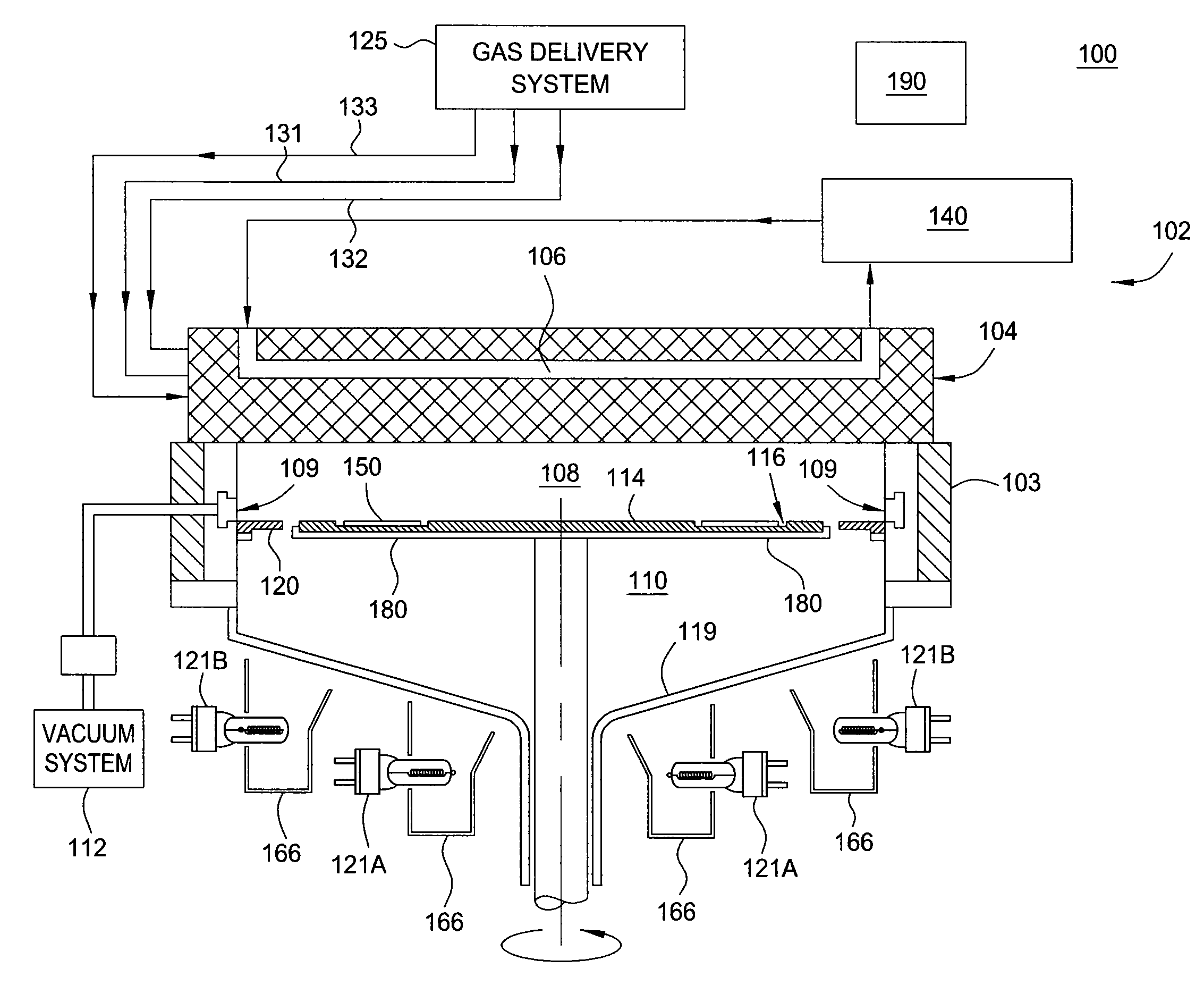
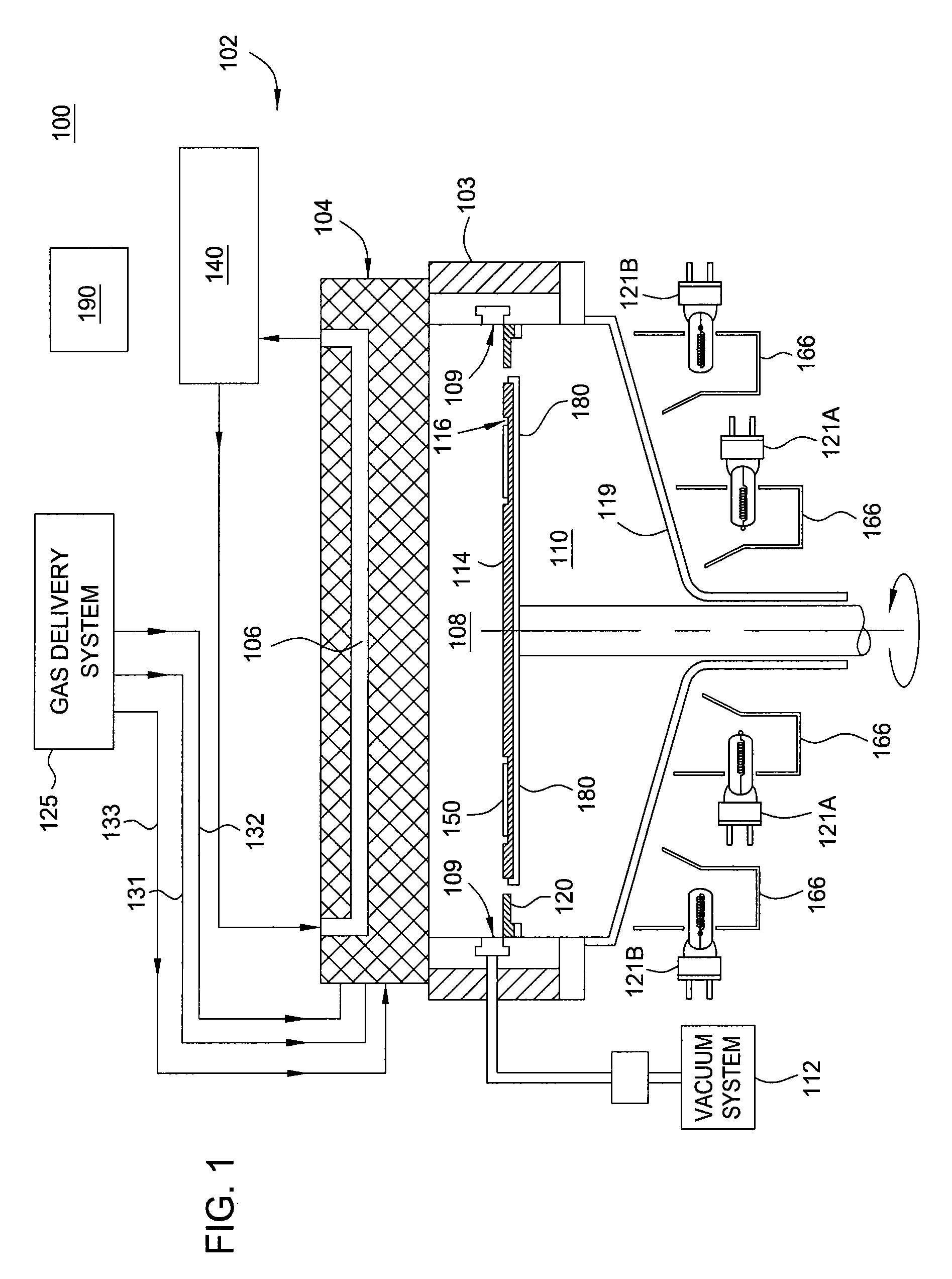
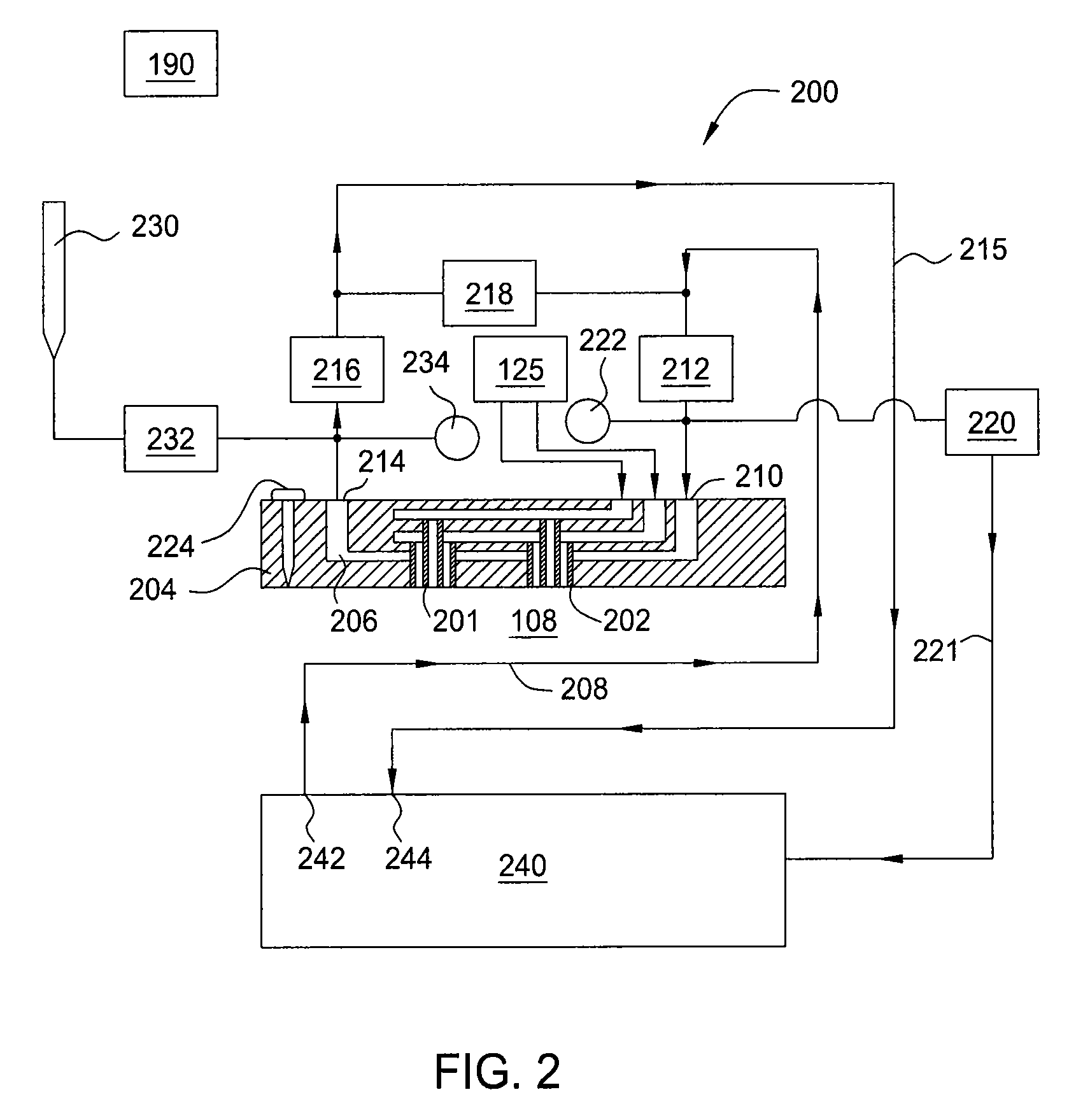
[0008]In one embodiment of the present invention, a deposition apparatus comprises a deposition chamber having one or more walls, a temperature controllable showerhead, and a substrate support defining a processing volume therein, a heat source proximate the deposition chamber, a first temperature sensor disposed within the deposition chamber, a first shut-off valve positioned to control flow of coolant into the showerhead from a coolant supply line, a second shut-off valve positioned to control flow of coolant from the showerhead into a coolant return line, a bypass valve in fluid communication with the coolant supply line upstream from the first shut-off valve and in fluid communication with the coolant return line downstream from the second shut-off valve, and a system controller in communication with the first temperature sensor...

Problems solved by technology

However, undesirable deposits also form on other chamber components, such as the precursor introducing showerhead, which therefore, must be periodically cleaned.
Further, current cleaning methods either fail to adequately clean the deposits on the showerhead or require significant system downtime, further resulting in increased overall costs of production.

Method used


Image

  • Method and apparatus for dry cleaning a cooled showerhead
  • Method and apparatus for dry cleaning a cooled showerhead
  • Method and apparatus for dry cleaning a cooled showerhead

Examples


Embodiment Construction

[0015]The present invention generally provides a method and apparatus for cleaning a showerhead in a deposition chamber, such as a metal organic chemical vapor deposition (MOCVD) chamber. In one embodiment, the showerhead is cleaned without exposing the interior components of the chamber to the atmosphere outside of the chamber (i.e., in situ cleaning). In one embodiment, flow of liquid coolant through a cooling system that is in fluid communication with the showerhead is redirected to bypass the showerhead, and the liquid coolant is drained from the showerhead. In one embodiment, any coolant remaining after draining the showerhead is flushed from the showerhead via a pressurized gas source. In one embodiment, the showerhead is then heated to an appropriate cleaning temperature. In one embodiment, the flow of liquid coolant from the cooling system is then redirected to the showerhead. Thus, the entire process is performed with minimal change to the flow of coolant through the coolin...


PUM

PropertyMeasurementUnit
Temperatureaaaaaaaaaa

Abstract

The present invention generally provides a method and apparatus for cleaning a showerhead of a deposition chamber, such as a metal organic chemical vapor deposition (MOCVD) chamber. In one embodiment, the showerhead is cleaned without exposing the chamber to the atmosphere outside of the chamber (i.e., in situ cleaning). In one embodiment, flow of liquid coolant through a cooling system that is in fluid communication with the showerhead is redirected to bypass the showerhead, and the liquid coolant is drained from the showerhead. In one embodiment, any remaining coolant is flushed from the showerhead via a pressurized gas source. In one embodiment, the showerhead is then heated to an appropriate cleaning temperature. In one embodiment, the flow of liquid coolant from the cooling system is then redirected to the showerhead and the system is adjusted for continued processing. Thus, the entire showerhead cleaning process is performed with minimal change to the flow of coolant through the cooling system.

Description

CROSS-REFERENCE TO RELATED APPLICATIONS[0001]This application claims benefit of U.S. Provisional Patent Application Ser. No. 61 / 231,117 (APPM / 013779L), filed Aug. 4, 2009, which is herein incorporated by reference.BACKGROUND OF THE INVENTION[0002]1. Field of the Invention[0003]Embodiments of the present invention generally relate to a method and apparatus for in situ dry cleaning a cooled showerhead in a deposition chamber. In particular, methods and apparatus are provided for automated showerhead coolant removal and refilling without discontinuing flow from a cooling system.[0004]2. Description of the Related Art[0005]Group III-V films are finding greater importance in the development and fabrication of a variety of semiconductor devices, such as short wavelength light emitting diodes (LED's), laser diodes (LD's), and electronic devices including high power, high frequency, high temperature transistors and integrated circuits. For example, short wavelength (e.g., blue / green to ultr...

Claims


Application Information

Patent Timeline
IPC IPC(8): C23C16/52B08B7/00
CPCC23C16/4405C23C16/45572C23C16/45565
Inventor GRIFFIN, KEVINKRYLIOUK, OLGASU, JIE
Owner APPLIED MATERIALS INC
Learn More