Heat dissipation structure and heat dissipation system adopting the same

a heat dissipation structure and heat dissipation system technology, applied in lighting and heating apparatus, modifications by conduction heat transfer, semiconductor/solid-state device details, etc., can solve the problem of affecting the heat dissipation efficiency of the thermal interface material

Inactive Publication Date: 2011-02-10
TSINGHUA UNIV +1
View PDF15 Cites 27 Cited by
  • Summary
  • Abstract
  • Description
  • Claims
  • Application Information

AI Technical Summary

Problems solved by technology

However, a heat conduction coefficiency of these thermal interface materials is now considered too low for many contemporary applications, because it cannot adequately meet the heat dissipation requirements of modern electronic components.
However, in use, when the carbon nanotubes 22 contact the heat sink or a heat source, the interface thermal resistance between the thermal interface material 40 and the heat sink or heat source is large because of the carbon nanotubes directly contacting the heat sink or heat source, thereby affecting the heat dissipation efficiency of the thermal interface material.

Method used


Image

  • Heat dissipation structure and heat dissipation system adopting the same
  • Heat dissipation structure and heat dissipation system adopting the same
  • Heat dissipation structure and heat dissipation system adopting the same

Examples


first embodiment

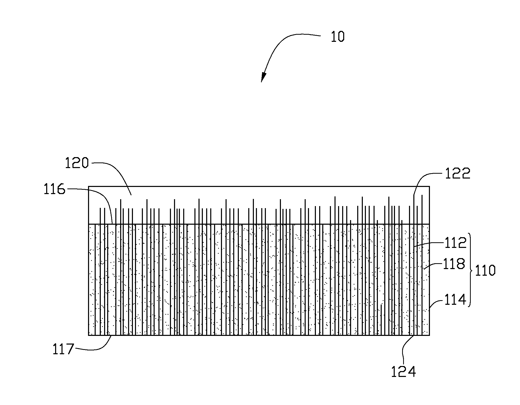
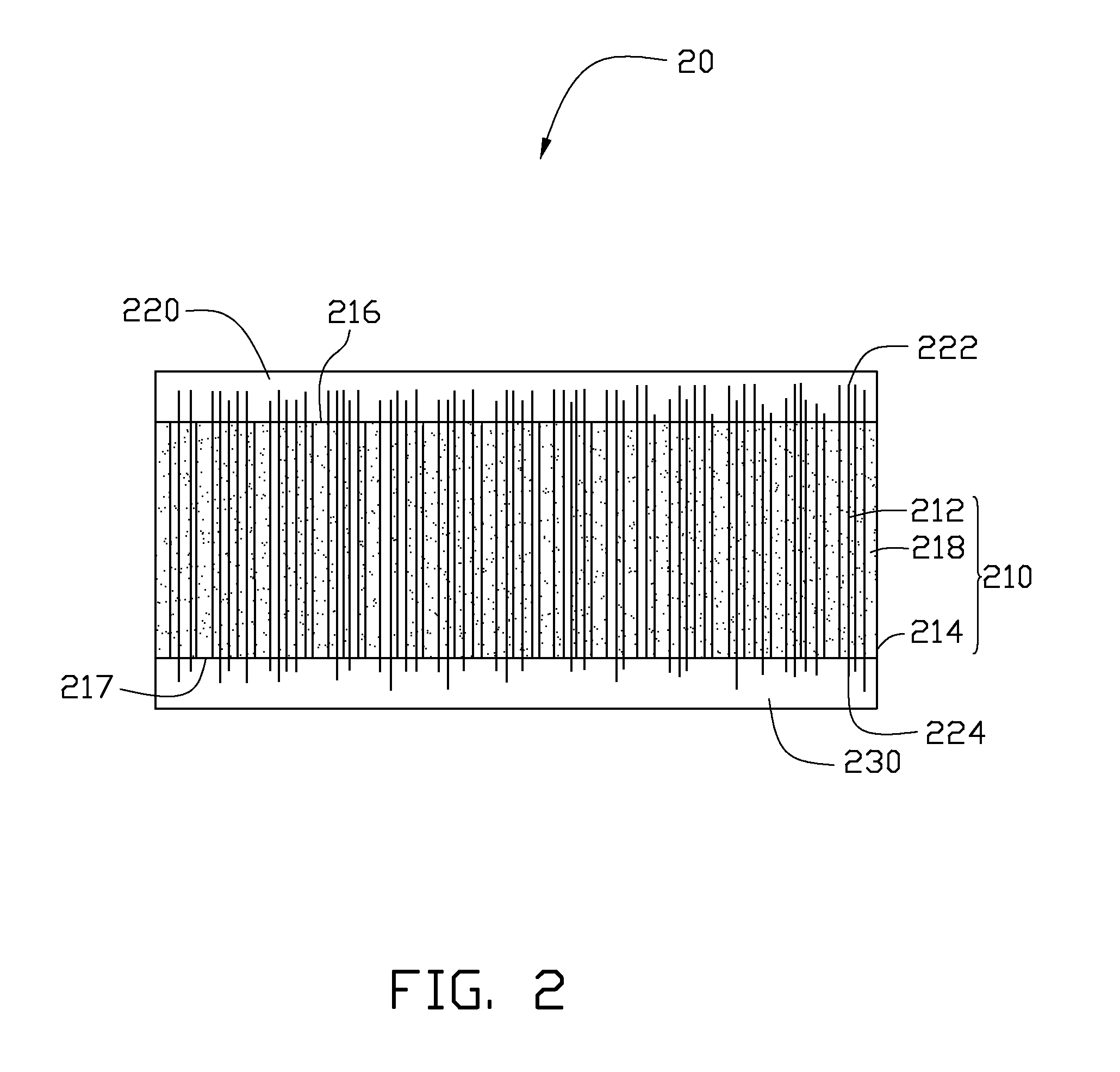
[0017]Referring to FIG. 1, a heat dissipation structure 10 includes a thermal interface material 110 and a transition layer 120. The thermal interface material 110 has a first surface 116 and a second surface 117 opposite to the first surface 116. The transition layer 120 is positioned on the first surface 116 of the thermal interface material 110.

[0018]The thermal interface material 110 includes a matrix 114 and a plurality of carbon nanotubes 112 dispersed in the matrix 114. A material of the matrix 114 includes a phase change material, such as resin material, thermal plastic, rubber, silicone, and a mixture thereof. The resin includes epoxy resin, acrylic resin or silicone resin. In one embodiment, the material of the matrix 114 is silicon elastomer kit.

[0019]The plurality of carbon nanotubes 112 can be substantially parallel to each other, and substantially perpendicular to the first surface 116 of the thermal interface material 110. One end of each of the plurality of carbon na...

second embodiment

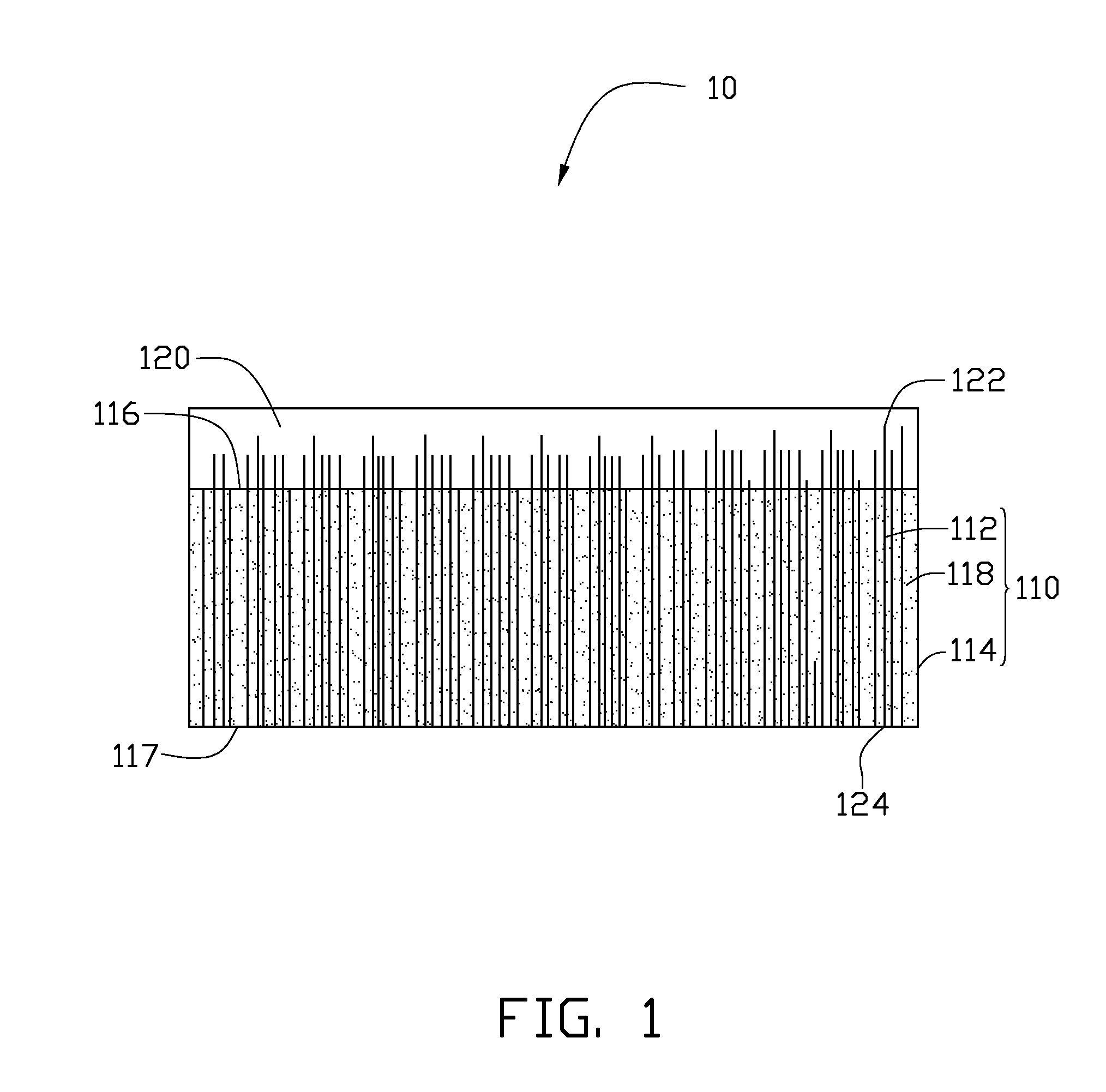
[0033]Referring to FIG. 2, a heat dissipation structure 20 includes a thermal interface material 210 and a first transition layer 220 and a second transition layer 230. The thermal interface material 210 includes a first surface 216 and a second surface 217 opposite to the first surface 216. The first transition layer 220 is positioned on the first surface 216 of the thermal interface material 210. The second transition layer 230 is positioned on the second surface 217 of the thermal interface material 210.

[0034]The thermal interface material 210 includes a matrix 214, a plurality of carbon nanotubes 212 and a plurality of thermal conductive particles 218. The plurality of carbon nanotubes 212 and the plurality of thermal conductive particles 218 are dispersed in the matrix 214. The plurality of carbon nanotubes 212 is substantially perpendicular to the first surface 216 of the thermal interface material 210. The plurality of carbon nanotubes 212 includes first ends 222 and second e...

third embodiment

[0039]Referring to FIG. 3, a heat dissipation structure 30 includes a thermal interface material 310 and a first transition layer 320 and a second transition layer 330. The thermal interface material 310 includes a first surface 316 and a second surface 317 opposite to the first surface 316. The first transition layer 320 is positioned on the first surface 316 of the thermal interface material 310. The second transition layer 330 is positioned on the second surface 317 of the thermal interface material 310.

[0040]The thermal interface material 310 includes a matrix 314, a plurality of carbon nanotubes 312 and a plurality of thermal conductive particles 318. The plurality of carbon nanotubes 312 and the plurality of thermal conductive particles 318 are dispersed in the matrix 314. The plurality of carbon nanotubes 312 is substantially perpendicular to the first surface 316 of the thermal interface material 310. The plurality of carbon nanotubes 312 includes first ends 322 and second e...


PUM

PropertyMeasurementUnit
thicknessaaaaaaaaaa
thicknessaaaaaaaaaa
mass percentaaaaaaaaaa

Abstract

A heat dissipation structure includes a thermal interface material and a transition layer. The thermal interface material includes a matrix and a plurality of carbon nanotubes dispersed in the matrix. The thermal interface material has a first surface and a second surface opposite to the first surface. The transition layer is positioned on one of the first surface or the second surface of the thermal interface material. A thickness of the transition layer is in a range from about 1 nanometer to about 100 nanometers. The transition layer is in contact with the carbon nanotubes of the thermal interface material. An interface thermal resistance between the transition layer and the heat source is less than that between the plurality of carbon nanotubes and the heat source. The present application also relates to a heat dissipation system adopting the heat dissipation structure.

Description

CROSS-REFERENCE TO RELATED APPLICATIONS[0001]This application claims all benefits accruing under 35 U.S.C. §119 from China Patent Application No. 200910109568.6, filed on Aug. 5, 2009 in the China Intellectual Property Office.BACKGROUND[0002]1. Technical Field[0003]The present disclosure relates to heat dissipation structures and heat dissipation systems and, particularly, to a heat dissipation structure and a heat dissipation system adopting the same.[0004]2. Description of Related Art[0005]Electronic components such as semiconductor chips are becoming progressively smaller, while heat dissipation requirements are increasing. A thermal interface material is commonly utilized between the electronic component and a heat sink to efficiently dissipate heat generated by the electronic component.[0006]A conventional thermal interface material is made by diffusing high heat conduction coefficiency particles in a base material. The particles can be made of graphite, boron nitride, silicon ...

Claims


Application Information

Patent Timeline
Patent Type & Authority Applications(United States)
IPC IPC(8): F28F21/02H01L23/373
CPCF28F21/02H01L23/373H01L2924/0002H01L2924/00F28F21/06F28F21/08F28F2013/006H01L23/3733H01L23/3737H05K7/2039
Inventor LIU, CHANG-HONGLI, QING-WEIFAN, SHOU-SHAN
Owner TSINGHUA UNIV
Why Eureka
Try Eureka