Integrated fluid filtration and recirculation system and method

a fluid filtration and recirculation system technology, applied in the direction of filtration separation, separation process, borehole/well accessories, etc., can solve the problems of inability to permanently store and treat cleaning fluid at the well location, inability to dispose of cleaning fluid, and inability to maintain the amount of cleaning fluid required, so as to achieve great economic savings and logistical savings

Inactive Publication Date: 2011-02-10
ENG FLUID SOLUTIONS
View PDF11 Cites 44 Cited by
  • Summary
  • Abstract
  • Description
  • Claims
  • Application Information

AI Technical Summary

Benefits of technology

[0013]In accordance with the present invention, a system and method are provided for an integrated fluid filtration and recirculation system that is especially adapted for filtering and re-circulating well cleaning and treatment fluid (referred to hereinafter collectively as “cleaning fluid”). With the method and system of the present invention, well cleaning fluid may be conserved by filtering and re-circulating used cleaning fluid back to the well for further cleaning operations. Thus, the cleaning fluid may be recycled a number of times before having to be evacuated from the site. The filtering and recycling of the cleaning fluid greatly conserves the amount of cleaning fluid required, and provides great economic savings and logistical savings with respect to the effort otherwise necessary to truck the cleaning fluid to and from the well locations.
[0014]The integrated fluid filtration and recirculation system of the present invention is characterized by a self-contained, automated, mobile / transportable, and efficiently sized system in which the cleaning fluid can be filtered and treated to a degree so that it may be reused in a number of subsequent cleaning cycles.

Problems solved by technology

The well tubulars may be particularly susceptible to corrosion, and deposits may develop on the tubulars such as silicates, sulfates, sulfides, carbonates, calcium and organic growth.
Because of environmental concerns in most locations, the cleaning fluids cannot be disposed of by allowing the fluid to be dumped onto the surrounding land.
The cleaning fluid cannot be permanently stored and treated at the well location and, therefore, once the cleaning fluid is spent, the cleaning fluid must be trucked offsite to a treatment facility.
Thus, one significant problem with well cleaning operations is the time and expense involved with trucking the needed cleaning fluid to and from the well locations.

Method used


Image

  • Integrated fluid filtration and recirculation system and method
  • Integrated fluid filtration and recirculation system and method
  • Integrated fluid filtration and recirculation system and method

Examples


Embodiment Construction

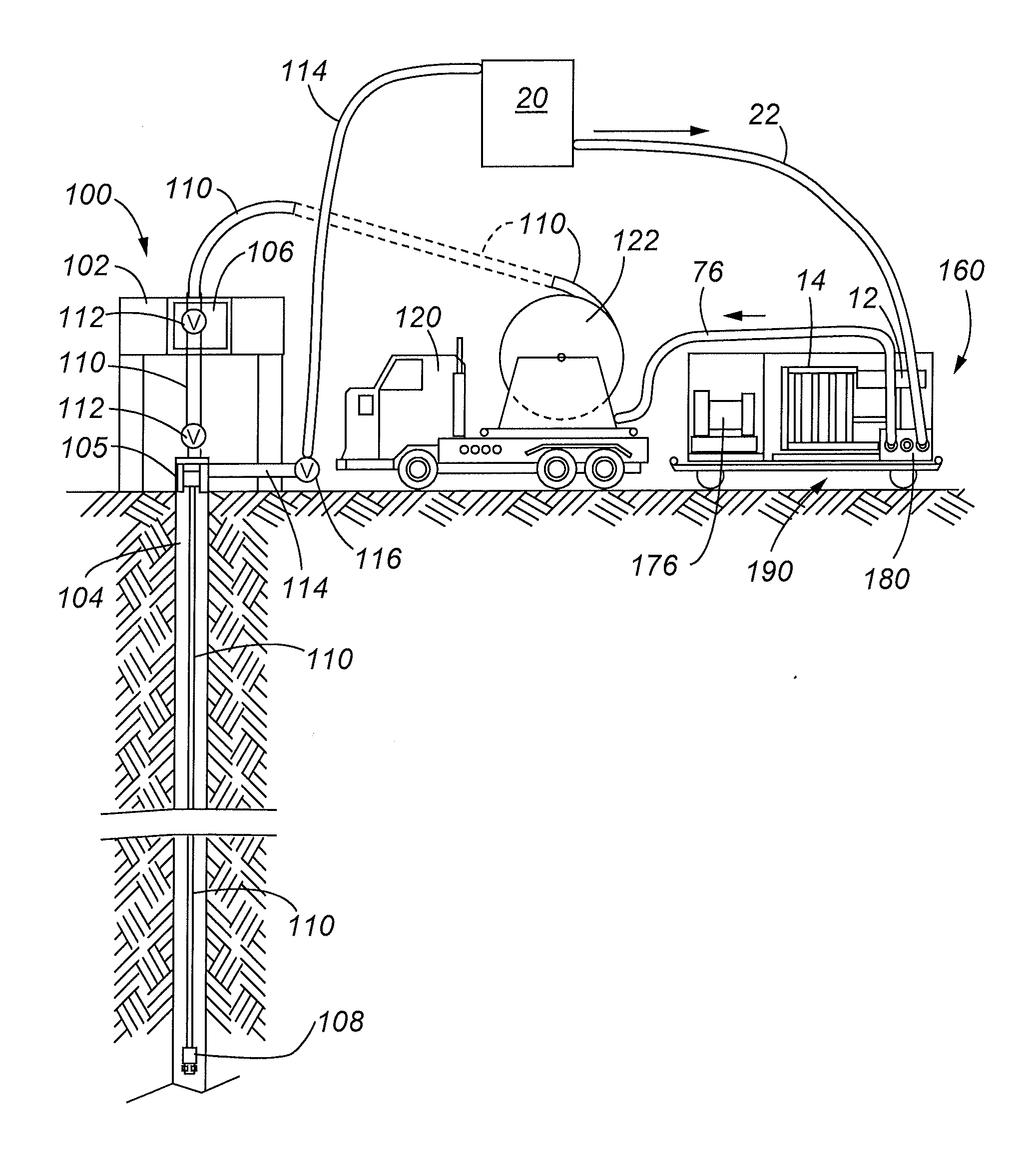
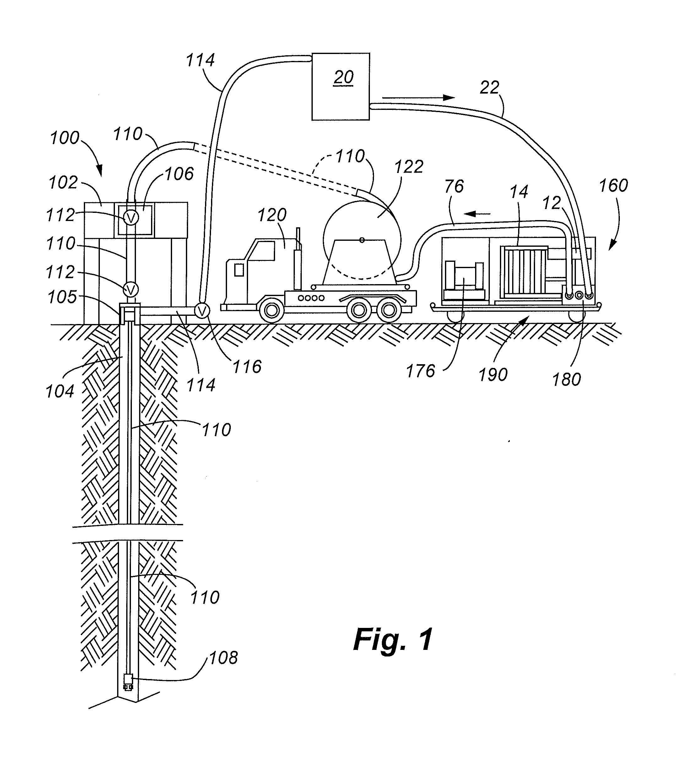
[0034]FIG. 1 illustrates a well 100 including a wellhead 102 that services a wellbore 104 that has been drilled. The well 100 may be, for example, a gas or oil producing well. A well casing 105 covers the wellbore 104. The wellbore 104 may be lined down-hole with various forms of tubulars (not shown). An injector assembly 106 is provided in the wellhead 102 for injecting cleaning fluid through coiled tubing 110 that has been placed in the wellbore. A cleaning apparatus 108 may be disposed at the distal end of the coiled tubing 110, and the apparatus 108 constitutes the most forward portion of the coiled tubing advanced through the wellbore. One or more control valves 112 may control the amount of cleaning fluid introduced through the coiled tubing 110. The cleaning fluid is introduced through the coiled tubing and strikes the wellbore once it discharges at the location of the cleaning apparatus 108. The used, discharged fluid then fills the wellbore and is evacuated through return l...


PUM

PropertyMeasurementUnit
lengthaaaaaaaaaa
lengthaaaaaaaaaa
pore sizesaaaaaaaaaa

Abstract

An integrated fluid filtration and recirculation system and method are provided for re-circulating and filtering fluid that is used in well cleaning operations. The system is incorporated within an enclosure, which is transportable, such as on a vehicle trailer. The system has power generation capability, thereby making the system capable of operating as a stand-alone unit. Chemicals may be infused into the filtered fluid from an integral chemical supply allowing the system to also function as a treatment facility for the fluid. The components of the system are arranged in a linear fashion that enables the system to maintain a minimum profile for transport upon a conventional trailer, yet the system provides enough room within the enclosure to allow operators to repair / inspect each of the system components. The enclosure may be climate controlled, and the enclosure may include removable panels for operation of the system in temperate conditions when climate control is unnecessary.

Description

FIELD OF THE INVENTION[0001]The present invention relates to self-contained, mobile, fluid filtration systems, and more particularly, to an integrated fluid filtration and recirculation system and method especially adapted for filtration and recycling of cleaning fluids used to clean the bore of a well.BACKGROUND OF THE INVENTION[0002]A number of systems have been developed for evacuating accumulations of blockages in wellbores to include oil and gas producing wells. The blockages may include accumulations of sediments and other solids generated from the well. A well is typically lined at the upper portion with a casing, and the down-hole portion is lined with metallic, plastic, or other liners, sometimes referred to as “well tubulars”. The tubulars may be in the form of production tubing, and slotted or wire-wrapped liners. The well tubulars may be particularly susceptible to corrosion, and deposits may develop on the tubulars such as silicates, sulfates, sulfides, carbonates, calc...

Claims


Application Information

Patent Timeline
Patent Type & Authority Applications(United States)
IPC IPC(8): E21B37/08B01D35/00B01D35/143B01D35/157E21B37/00
CPCE21B37/08
Inventor IRVINE, WILLIAM O.GALASSINI, BENJAMIN ALLEN
Owner ENG FLUID SOLUTIONS
Why Eureka
Try Eureka