Eureka AIR delivers breakthrough ideas for toughest innovation challenges, trusted by R&D personnel around the world.

A gate driver circuit basing on igzo process

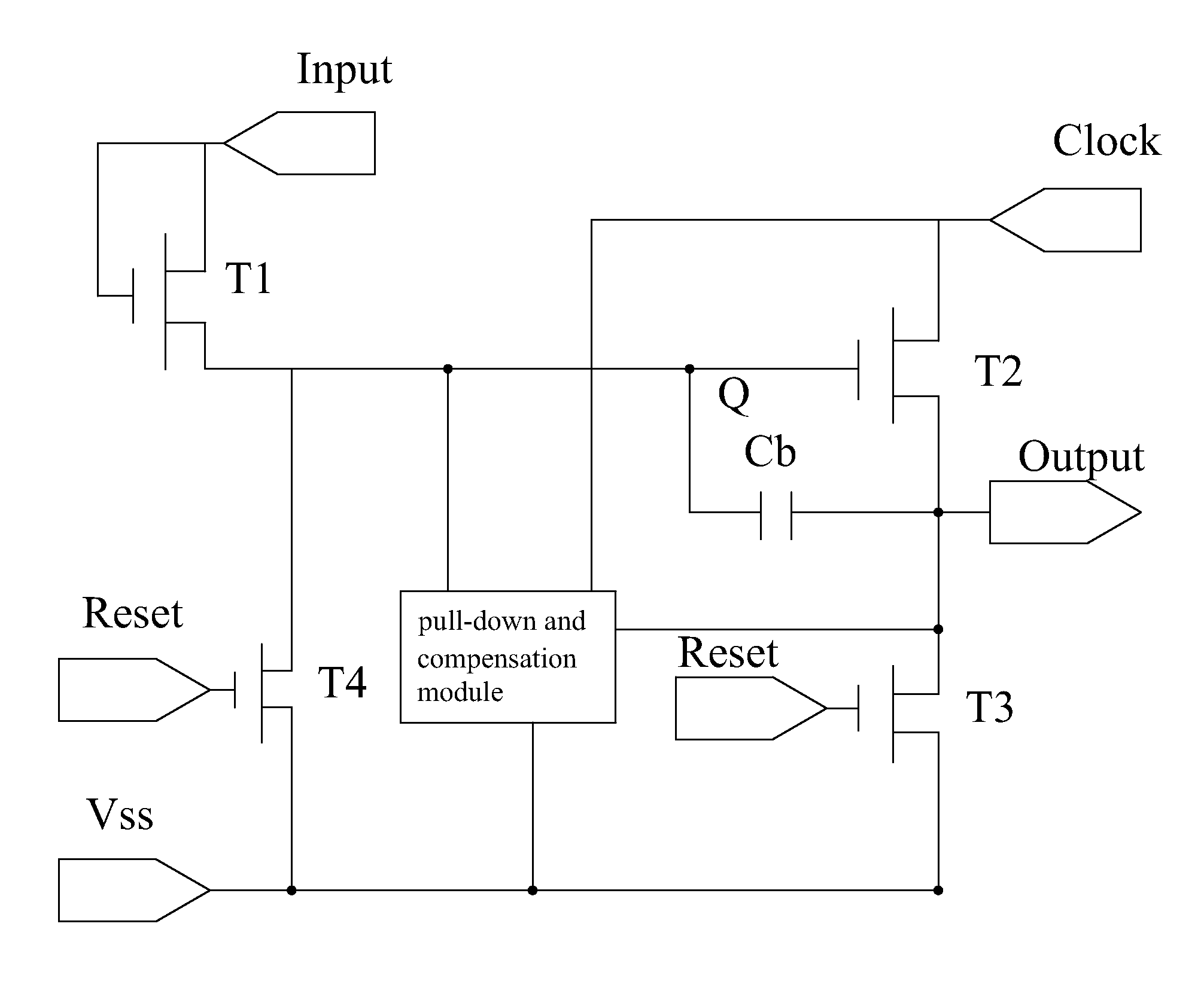
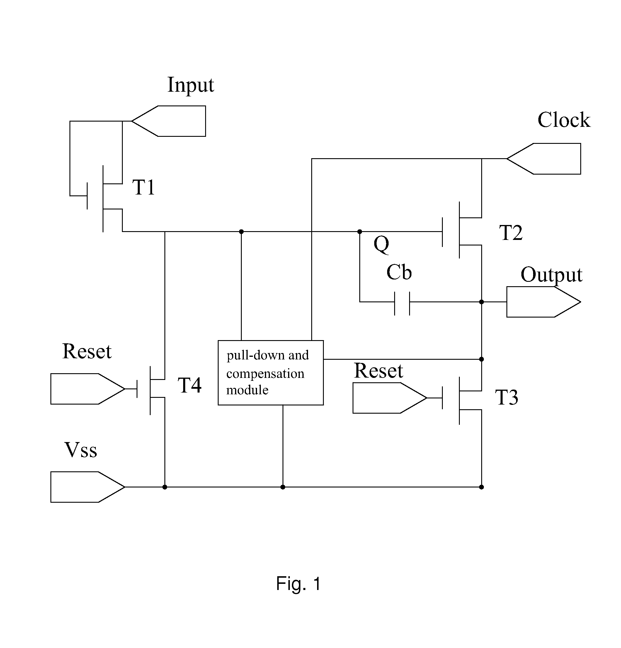
a gate driver and process technology, applied in the field of lcd, can solve the problems of failure of the goa of the igzo, electric leakage of the tft of the goa, etc., and achieve the effects of reducing the loading effect minimizing the delay of the first node, and helping to stabilize the output terminal output outpu

Active Publication Date: 2016-08-25
SHENZHEN CHINA STAR OPTOELECTRONICS TECH CO LTD
View PDF0 Cites 18 Cited by
  • Summary
  • Abstract
  • Description
  • Claims
  • Application Information

AI Technical Summary

Benefits of technology

The present invention provides a gate driver circuit based on IGZO process to save expenses and time in LCD display production. It prevents electrical leakages of TFTs, reduces the amount of TFTs, parasitic capacitances, and electricity consumption. It uses three gradually decreasing negative supplies, the first node, and the second node to pull down the driving signal potential and stabilize the first node, reducing the loading effect. The pull-down part directly connecting the driving signal terminal pulls down the first node faster and minimizes the delay. The one-side asymmetric pull-down holding design effectively saves the amount of TFTs, reduces parasitic capacitances, and saves consumption of electrical circuits.

Problems solved by technology

Thus these issues will lead to electrical leakages of TFTs of the GOA and fails of the GOA of the IGZO.

Method used


Image

  • A gate driver circuit basing on igzo process
  • A gate driver circuit basing on igzo process
  • A gate driver circuit basing on igzo process

Examples


first embodiment

[0031]Please refer to FIG. 3, FIG. 7 and FIG. 8 which show the gate driver basing on IGZO process of the present invention. The gate driver circuit basing on IGZO process comprises GOAs working of the cascade. Wherein the N is a positive integer. The Nth-stage GOA comprises: a pull-up control part 100, a pull-up part 200, a transfer part 300, a pull-down part 400, a pull-down holding part 500, a boost part 600.

[0032]The said pull-up part 200 comprises a first transistor T1. The gate of the first transistor T1 electrically connects a first node Q(N), the source of the first transistor T1 electrically connects a first clock signal CK, the drain of first transistor T1 electrically connects an output terminal G(N). The first transistor T1 is used for outputting the signal from the output terminal G(N) according to the first clock signal CK.

[0033]The said transfer part 300 comprises the second transistor T2. The gate of the second transistor T2 electrically connects the first node Q(N), ...

third embodiment

[0061]Besides, showed as FIG. 10, in the third embodiment, the gate of eleventh transistor T11 and twelfth transistor T12 electrically connect the driving signal terminal ST(2) of the second-stage GOA within the last-stage connection of the gate driver basing on IGZO process.

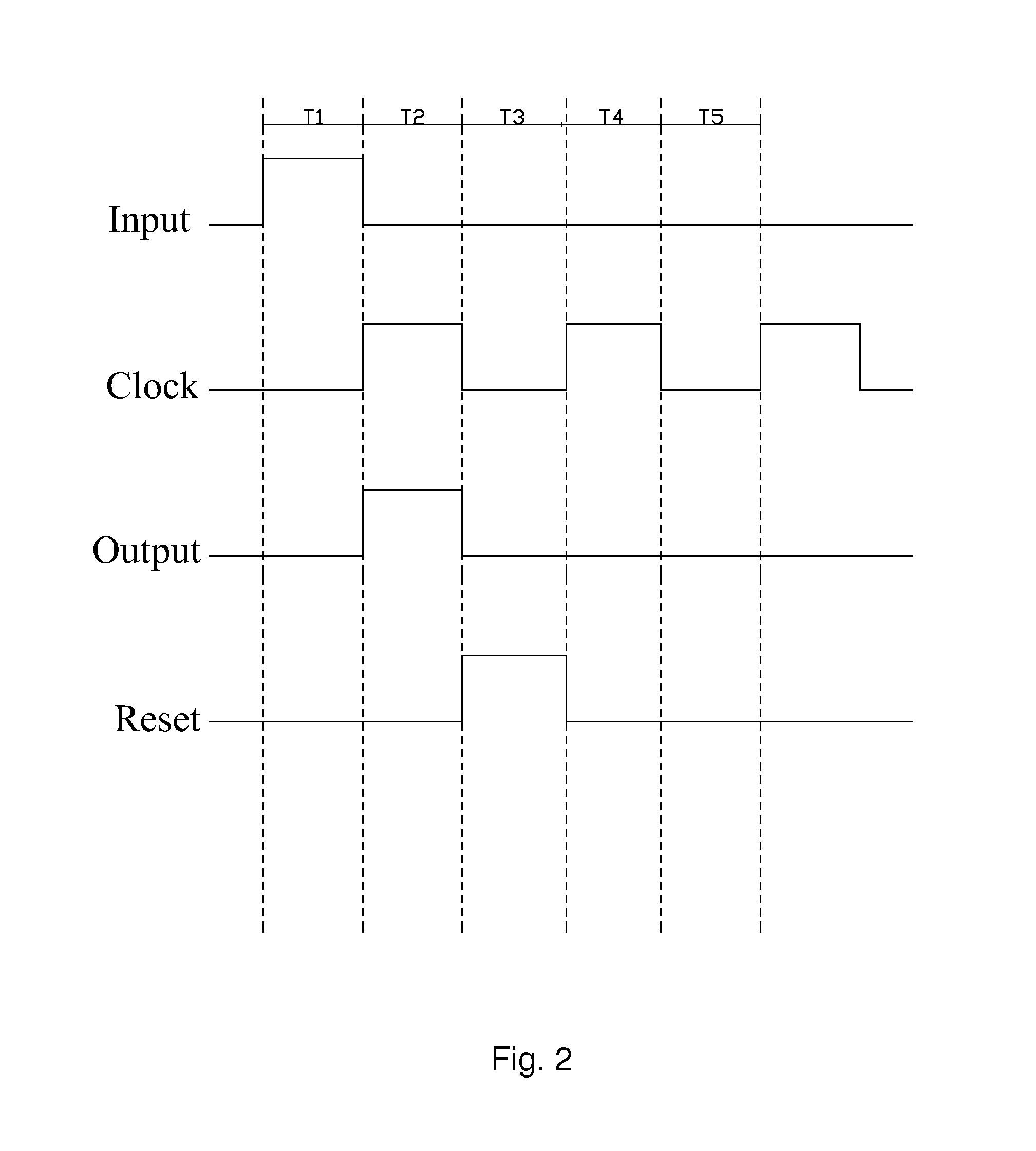
[0062]Please refer to the FIG. 11, the simulation of the 60 stages GOA of the embodiment of the gate driver basing on IGZO process of the present invention shows well outputs.

[0063]In summary, the gate driver basing on IGZO process of the present invention using three gradually decreasing negative supplies, the first node, and the second node shall pull down the electrical potential of the driving signal to overcome the electrical leakage of the TFTs of the gate driver with IGZO process. Besides, the gate driver of the present invention using the driving signal to handle the electrical potential of the second node shall reduce the loading effect of the first node, stabilize the first node well and it is helpful ...


PUM


Abstract

The present invention provides a gate driver basing on IGZO process, comprising: GOAs in cascade connection comprising a Nth-stage GOA, wherein the Nth-stage GOA further comprising: a pull-up control part 100, a pull-up part 200, a transfer part 300, a pull-down part 400, a pull-down holding part 500, a boost part 600, a first negative supply VSS1, a second negative supply VSS2, a third negative supply VSS3, which are three gradually decreasing negative supplies and pull down an output terminal G(N), a first node Q(N), a second node P(N), and a driving single ST(N) to prevent the electrical leakage of TFTs effectively. And channels of the TFT switches of the gate driver basing on the IGZO process are oxide semiconductor channels.

Description

TECHNICAL FIELD[0001]The present invention relates to LCD field, especially relating to a gate driver basing on IGZO process.DESCRIPTION OF RELATED ART[0002]The GOA (Gate Driver On Array) is a skill providing gate divers on TFT array substrates to scan line by line. A GOA circuit comprises a pull-up part, a pull-up control part, a transfer part, a pull-down part, a pull-down holding part, and a boost part.[0003]A pull-up part is used for sending clock signals to the gates of TFT to provide driving signals of a LCD. A pull-up control part is used for controlling the pull-up part by signals from a former stage GOA usually. The pull-down part is used for pulling the scanning signal, i.e. the electrical potential of the gate of the TFT, to low level after sending out scanning signals. A pull-down holding part is used for maintaining scanning signals and the signals of the pull-up part, i.e. the signal of node Q, in closing state, which is the predetermined negative potential; and there ...

Claims


Application Information

Patent Timeline
Patent Type & Authority Applications(United States)
IPC IPC(8): G09G3/36G11C19/28
CPCG09G3/36G09G3/3677G11C19/28G09G2300/0871G09G2310/0286G09G2300/0465G09G2300/0408
Inventor XIAO, JUNCHENG
Owner SHENZHEN CHINA STAR OPTOELECTRONICS TECH CO LTD
Why Eureka
Eureka Blog
Learn More