
Water treatment apparatus and a method for cleaning a filter layer of a water treatment apparatus

a technology of water treatment apparatus and filter layer, which is applied in the direction of filtration separation, sedimentation settling tank, separation process, etc., can solve the problems of iron and manganese contents in underground water, water unsuitable for drinking, and various difficulties in these industries

Active Publication Date: 2012-02-07
NAGAOKA INT
View PDF72 Cites 18 Cited by
  • Summary
  • Abstract
  • Description
  • Claims
  • Application Information

AI Technical Summary

Benefits of technology

[0020]Studies and experiments made by the inventors of the present invention for achieving the above objects of the invention have resulted in the finding, which has led to the present invention, that, in view of the fact that a major part of iron to be caught by a water treatment apparatus settles in the upper portion of the filter layer while a major part of manganese settles in the lower portion of the filter layer and that concentrations of iron and manganese in raw water are not equal but concentration of iron is normally much higher than concentration of manganese, a cleaning effect of removing iron in the upper portion of the filter layer can be remarkably improved by cleaning the filter layer in such a manner that a swirl stream or a random stream is formed in the water above the surface of the filter layer. The inventors have also found that the cleaning effect can be remarkably improved by removing iron by a partial cleaning process and removing manganese by a whole cleaning process whereby a high speed filtering which has not been achieved in the prior art water treatment apparatus can be realized and the amount of cleaning water can be significantly saved.

Problems solved by technology

In these industries, iron and manganese contents contained in underground water have raised a problem.
While iron and manganese are substances which are necessary for a human body, contents of these substances exceeding a certain amount give a metal taste to water and turn water to red or black water, thereby making the water unsuitable for drinking and causing various difficulties in these industries.
In the conventional water treatment device requiring addition of an oxidizing agent or a flocculant, however, a relatively large amount of oxidizing agent or flocculant is consumed in the device and, therefore, the cost of such oxidizing agent or flocculant is tremendous.
Further, since hypochlorous acid which is used as the oxidizing agent remains in water after the treatment for oxidizing iron and manganese, trihalomethane which is a carcinogen is generated and, for removing trihalomethane, the water must further be filtered through an activated carbon layer which adds to the cost of the water treatment.
This method requires a high cost of maintenance in addition to the cost of purchasing the oxidizing agent.
Further, the conventional water treatment device generally is a complex and large-scale system including an aeration tank, a flocculation tank, a precipitation tank, a sand filter tower, an iron and manganese removing tower and a chemical agent tank and this system requires a large space for installation.
It is impossible to install such a large device in a site of a limited space such in a town.
Furthermore, filtering sand which is used in this water treatment device requiring addition of an oxidizing agent is blocked by accumulated impurities and therefore must be replaced from time to time.
The used sand to be abandoned must be treated as industrial waste because it contains a chemical agent and a place where it can be abandoned is extremely restricted by laws and regulations.
In the prior art water treatment apparatuses including one disclosed in the above described publication, iron which is made insoluble and deposited in the form of a film on the filter material tends to be removed excessively in the lower portion of the filter layer and removed insufficiently in the upper portion of the filter layer when the filter layer is cleaned with cleaning water.
If, in a case where concentration of iron in raw water is significantly larger than concentration of manganese, the filter layer as a whole is cleaned with a large quantity of cleaning water for removing iron caught in the upper portion of the filter layer, microorganism living in the lower portion of the filter layer for catching manganese will be washed away and, as a result, catching of manganese in a subsequent water treatment operation will be obstructed.
Particularly, space for establishing a water treatment apparatus is limited because a location at which such apparatus can be established is limited.
Accordingly, unless cleaning of the filter layer is conducted efficiently, increase in the filtering speed cannot be achieved.
In a case where it is necessary to increase the filtering speed of filter operation, cleaning of the filter layer must also be made more frequently and burden to treatment imposed by microorganism in the lower portion of the filter layer also increases.
Therefore, efficiency of cleaning of the filter layer by this water treatment apparatus is limited to the above described filtering speed and a higher filtering speed cannot be achieved.
The prior art water treatment apparatus including one described in the above described publication must consume about 10% to 15% of received water (filtered water) for the above described cleaning operation with the result that efficiency of water treatment is significantly reduced.
Since this mechanism must reciprocate the raw water supply tube with an electric motor, a large power is required for cleaning the surface of the filter layer and a complex mechanism for reciprocation of the raw water supply tube.
Further, this water treatment apparatus requires much labor and cost for maintenance of the apparatus including compensation for wear of rails for reciprocating the raw water supply tube and wear of a hose for supplying raw water to the raw water supply tube.
Furthermore, for moving the raw water supply tube in which the cleaning nozzles are disposed in a line, the filtering tank must have a rectangular configuration with resulting increase in the size of the apparatus.
Thus, it is difficult to make a compact design of the apparatus even in case the apparatus must be established in a narrow space.
Further, in the prior art water treatment apparatus in which cleaning of the filter layer is made by reciprocating the cleaning nozzles, the surface of the filter layer other than areas where the cleaning nozzles pass over remains uncleaned and hence it takes much time to complete cleaning of the entire surface of the filter layer resulting in difficulty in achieving a high speed cleaning of the filter layer.

Method used


Image

  • Water treatment apparatus and a method for cleaning a filter layer of a water treatment apparatus
  • Water treatment apparatus and a method for cleaning a filter layer of a water treatment apparatus
  • Water treatment apparatus and a method for cleaning a filter layer of a water treatment apparatus

Examples


Embodiment Construction

[0083]Preferred embodiments of the invention will now be described with reference to the accompanying drawings.

[0084]The present invention can be applied not only to a water treatment apparatus comprising two filter layers of an upper layer and a lower layer but also to a water treatment apparatus comprising a single filter layer. In the following description, description will be made about a preferred embodiment of a water treatment apparatus having two filter layers of an upper layer and a lower layer.

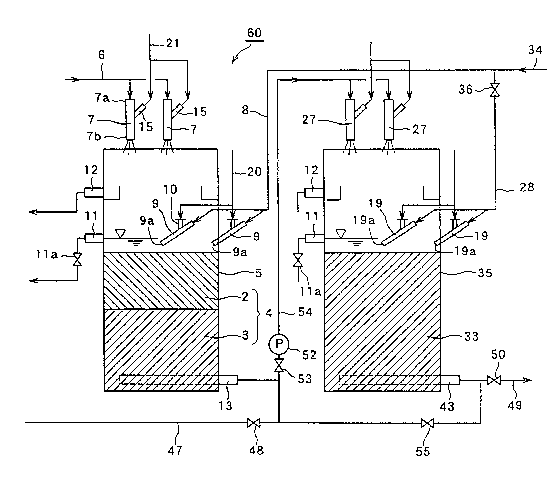
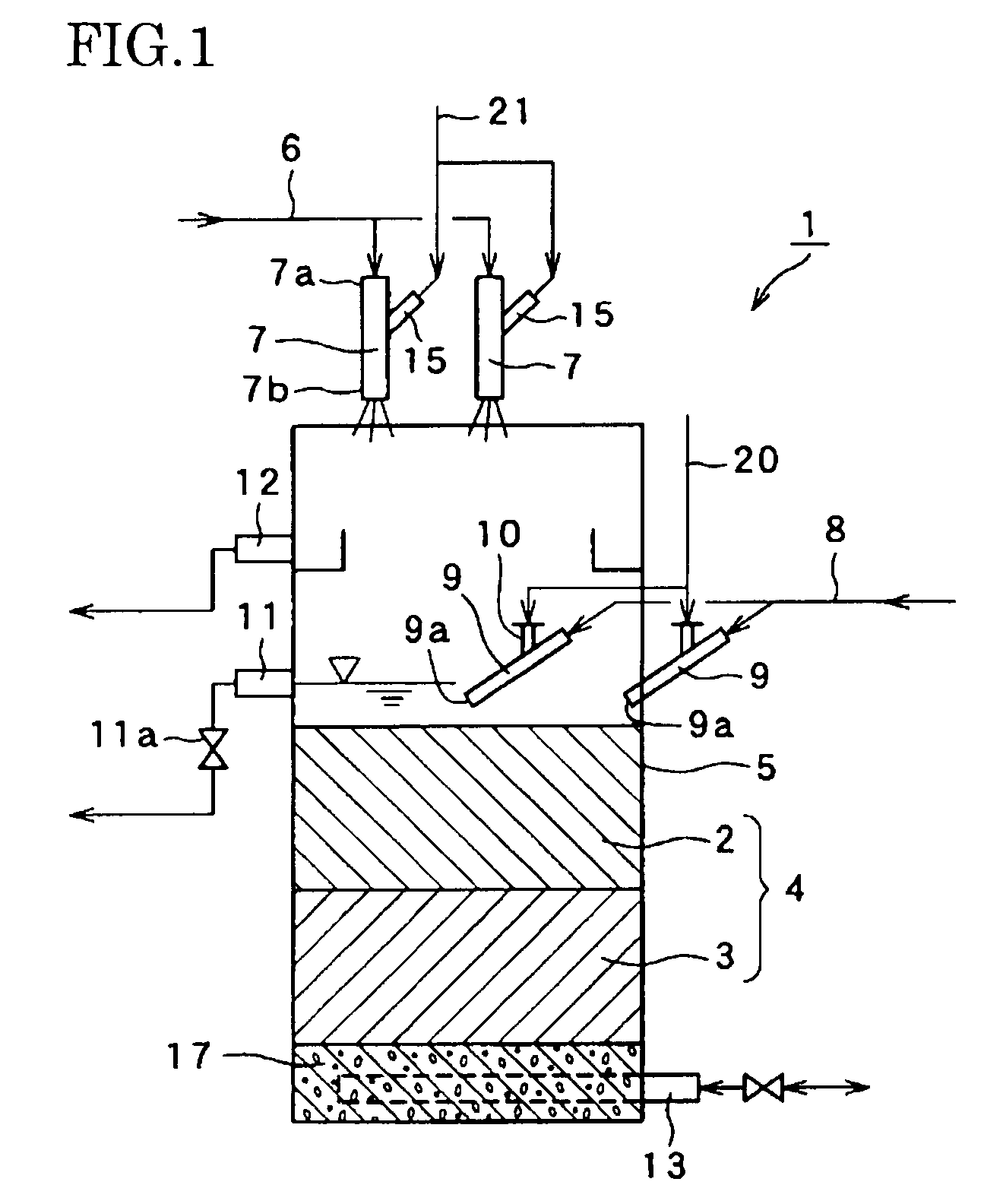
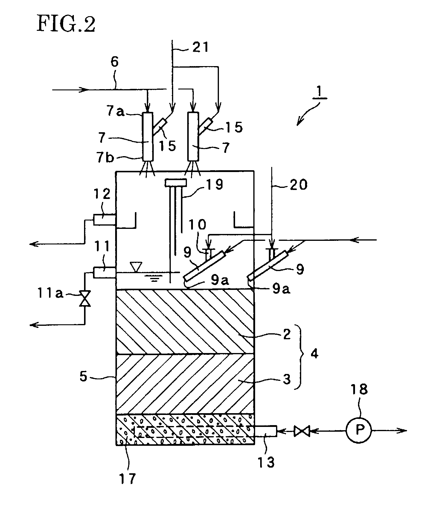
[0085]FIG. 1 is a diagram showing schematically an embodiment of the water treatment apparatus of the invention. FIG. 2 is a diagram showing schematically another embodiment of the water treatment apparatus. FIG. 3 is a plan view showing disposition of upper layer cleaning jet nozzles used in the embodiments of FIGS. 1 and 2.

[0086]In FIG. 1, A water treatment apparatus 1 comprises, as main component elements, a filtering tank 5 housing a filter layer 4 consisting of an upper layer 2 ...


PUM

PropertyMeasurementUnit
filtering speedaaaaaaaaaa
speedaaaaaaaaaa
speedaaaaaaaaaa

Abstract

A water treatment apparatus includes a raw water supply tube, mixed raw water stream jet nozzles each communicating at one end thereof with the raw water supply tube and having at the other end thereof a raw water outlet from which mixed stream of raw water and air is jetted out, a filtering tank housing a filter layer disposed below the mixed raw water stream jet nozzles with a predetermined distance between the surface of the filter layer and the raw water outlet of the mixed raw water stream jet nozzles, a filtered water takeout tube provided in the filtering tank for taking out water filtered through the filter layer, a reverse stream cleaning water supply tube provided in the filtering tank for supplying reverse stream cleaning water to the filter layer, filter layer cleaning jet nozzles each communicating at one end thereof with a filter layer cleaning water supply tube and having at the other end thereof a cleaning water outlet from which cleaning water is jetted out, and an overflow outlet provided in the filtering tank above the filter layer.

Description

TECHNICAL FIELD[0001]This invention relates to a water treatment apparatus and, more particularly, to a water treatment apparatus which can oxidize iron, manganese and other substances dissolved in water such as underground water to turn them into substances which are insoluble in water with a simple and compact apparatus and without using a chemical such as an oxidizing agent or a coagulant. The invention relates also to a method for cleaning a filter layer of such water treatment apparatus.BACKGROUND ART[0002]Underground water is utilized as raw water for tap water and also utilized in industries which require a large quantity of water such as food, soft drink, beverage, dyestuff industries and also in public baths. In these industries, iron and manganese contents contained in underground water have raised a problem. While iron and manganese are substances which are necessary for a human body, contents of these substances exceeding a certain amount give a metal taste to water and ...

Claims


Application Information

Patent Timeline
Patent Type & Authority Patents(United States)
IPC IPC(8): B01D37/00B01D24/46
CPCB01D24/10B01D24/4631B01D24/4621C02F1/001C02F2101/203C02F2101/206C02F2303/14C02F2303/16B01D24/46B01D24/02
Inventor MIMURA, HITOSHIMUKAI, KIYOKAZU
Owner NAGAOKA INT
Learn More