Architectures and Methods for Novel Antenna Radiation Optimization via Feed Repositioning

a technology of antenna radiation optimization and feed repositioning, applied in the direction of collapsible antenna means, antenna details, antennas, etc., can solve the problem of needing to increase the constraints of ground terminals for both transmit and receive functions, and achieve the effect of cost-effective and complex satellite antenna design

Active Publication Date: 2011-02-10
SPATIAL DIGITAL SYST
View PDF9 Cites 49 Cited by
  • Summary
  • Abstract
  • Description
  • Claims
  • Application Information

AI Technical Summary

Benefits of technology

[0025]The present invention relates to satellite and ground terminal antenna architectures and wireless communications, specifically satellite and ground terminal based communications. Specifically, the present invention provides a dynamic method and design of using a dynamic antenna array system to utilize beam forming, null shaping, and feed repositioning as an elegant solution to: overlapping GEO satellite-based interference, a cost effective method to complex satellite antenna design.

Problems solved by technology

However, as the number of satellites in the Earth's geo-synchronous orbit increases due to rising demand, the need rises for additional constraints on ground terminals for both transmit and receive functions-beam nulling.
However, these coverage areas must be determined during the design phase as the reflector shape must be manufactured under the constraints of known potential coverage areas.

Method used


Image

  • Architectures and Methods for Novel Antenna Radiation Optimization via Feed Repositioning
  • Architectures and Methods for Novel Antenna Radiation Optimization via Feed Repositioning
  • Architectures and Methods for Novel Antenna Radiation Optimization via Feed Repositioning

Examples


Embodiment Construction

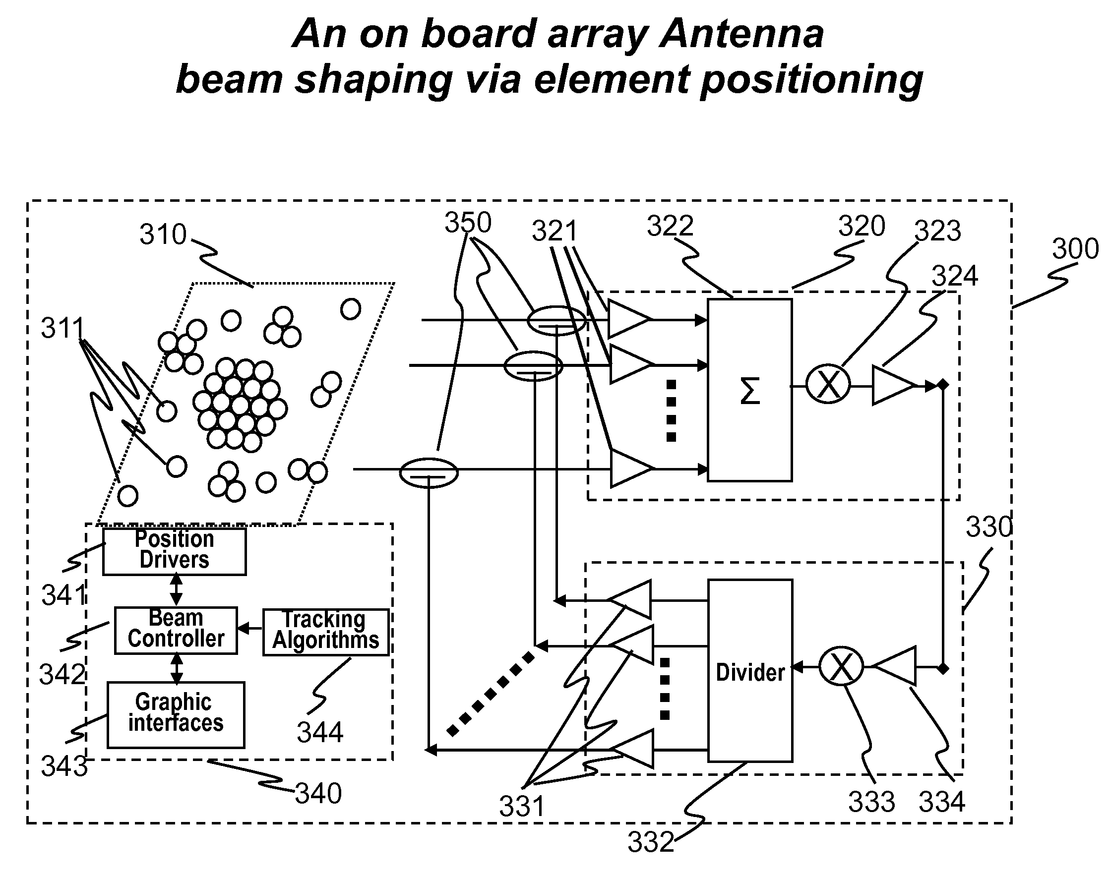
[0067]Mechanical feed position adjustment techniques can be applied in a cost effective manner to many antenna designs for reconfigurable coverage in various applications. In this disclosure, we list 6 different applications related to satellite communications. However, the same techniques can be utilized in many applications, including but with no limitation thereto, cell phone base stations, terrestrial point-to-point connectivity, point-to-multi-point connectivity, two way ground to air and air to ground communications links.

[0068]The present invention may perform any of the following functions for an antenna on satellites via feed repositioning:[0069]1. Shaping the antenna radiation pattern for either transmit or receive beams to prescribed contours covering a service area.[0070]2. Shaping the antenna radiation pattern for both transmit and receive beams to prescribed contours covering a service area.[0071]3. Configurability; to re-shape the radiation pattern to various contours...


PUM


Abstract

The present invention relates to antenna architectures and methods on re-configurable multi-element antennas via feed re-positioning for various optimized radiation contours, including beam forming (or shaping) and/or null steering on contoured beams, spot beams, and orthogonal beams. The feed re-positioning techniques can also be used in radiation pattern optimization processing during antennas designing phases for fixed beams. The techniques are applicable for satellite communications. For satellite antennas, the beam shaping capability via element repositioning can be utilized for (1) optimized geometries on satellite antennas for given desired coverage areas, (2) re-optimizing radiation contours for reconfigurable antenna on board satellites in operation, (3) additional flexibility for satellite antennas using ground based beam forming (GBBF). As to satellite ground terminals, the same techniques are applicable for both fixed and mobile satellite terminals featuring either single beam or multiple beams. For fixed terminals, are applicable for terrestrial based communications; such as retrofitting existing antennas eliminating interference radiations coming from fixed or slow varying directions.

Description

RELATED APPLICATION DATA[0001]This application claims the benefit, pursuant to 35 U.S.C. §119(e), of U.S. provisional application Ser. No. 61 / 273,502 filed on Aug. 5, 2009.REFERENCES[0002]1. U.S. Pat. No. 6,633,744, “Ground-based satellite communications nulling antenna,” James M Howell, Issued on Oct. 14, 2003.[0003]2. U.S. Pat. No. 6,844,854, “Interferometric antenna array for wireless devices,”: J. R. Johnson, S L. Myers, Issued date: Jan. 18, 2005[0004]3. U.S. Pat. No. 5,739,788, “Adaptive Receiving Antenna for Beam Repositioning,” R. B. Dybdal and S. J. Curry, Issued on April, 1998.[0005]4. U.S. Pat. No. 5,440,306, “Apparatus and Method for Employing Adaptive Interference Cancellation over a Wide Bandwidth,” R. B. Dybdal and R. H. Ott, Issued on Aug. 8, 1995.[0006]5. “Acceleration on the synthesis of shaped reflector antennas for contoured beam applications via Gaussian beam approach,” H. T. Chou, W. Theunissen, P. H. Pathak, IEEE Antennas and Propagation Society International ...

Claims


Application Information

Patent Timeline
Patent Type & Authority Applications(United States)
IPC IPC(8): H01Q3/01
CPCH01Q3/04H01Q19/132H01Q19/10H01Q3/06H01Q3/40H01Q19/12
Inventor CHANG, DONALD C. D.LIN, MICHAEL T. S.HU, ERIC
Owner SPATIAL DIGITAL SYST
Why Eureka
Try Eureka