System for Emulating Continuous Pan/Tilt Cameras

a technology of pan/tilt camera and system, applied in the field of cameras, can solve the problems of affecting the quality of the image, and the twisting of the connection, etc., and achieve the effect of reducing the size of the compressed imag

Inactive Publication Date: 2011-02-10
PELLING NICHOLAS JOHN
View PDF14 Cites 45 Cited by
  • Summary
  • Abstract
  • Description
  • Claims
  • Application Information

AI Technical Summary

Benefits of technology

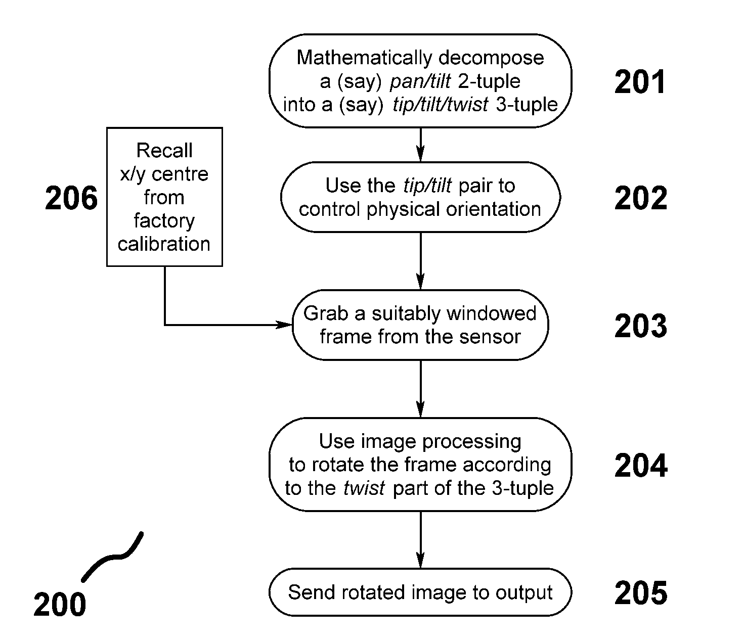
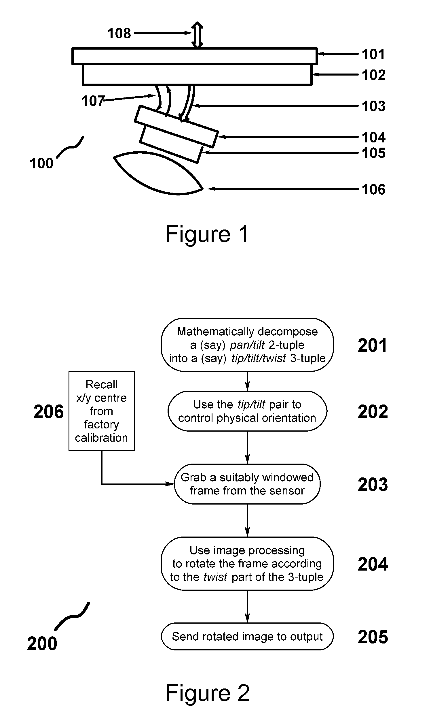
[0025]In one embodiment a system for emulating a continuous pan/tilt camera is presented. The system includes means for capturing an image, means for orientating the capturing means to capture the image within a hemispherical space and means for rotating the captured image to emulate the continuous pan/tilt camera. In another embodiment the means for orientating further includes a tip/tilt orientation mechanism. Yet another embodiment further includes means for adjusting the capturing ...

Problems solved by technology

However, the fact that a wall-mounted camera is necessarily positioned on a wall is a significant handicap, because this placement often has a restricted or occluded view of the scene (i.e., objects are in the way), while in the context of a room, the far wall can be a long way off.
However, in prior art cameras this favorable position comes at a cost.
However, such unconstrained rotation quickly leads to a constructional problem with the electrical connections between the camera subunit and the unit's main casing.
As an unconstrained pan spins the camera subunit around, all of the electrical connections between the camera subunit and the main casing twist and tighten, ultimately causing those connections (e.g., on a ribbon cable) to twist and sometimes break as a result of the unconstrained twisting that is applied to them.
However, this has the side effect that when a camera hits either end-stop, if the user wishes to continue tracking in the same direction they must first laboriously ro...

Method used


Image

  • System for Emulating Continuous Pan/Tilt Cameras
  • System for Emulating Continuous Pan/Tilt Cameras
  • System for Emulating Continuous Pan/Tilt Cameras

Examples


third embodiment

[0055]Referring to FIG. 4C, by way of comparison, a third embodiment expresses the idea of “breaking out” the post-processing rotation stage into a separate unit. This may be beneficial for various reasons. For example, without limitation, the separate post-processing unit may be independently sold as a unit for converting dynamic wall-mounted cameras into ceiling-mounted units, or separating the post-processing unit from the camera may enable the camera to be smaller. In the present embodiment, rotation means 405 and orientation transformation means are embodied in an external box 433 connected to a constrained-range wall-mount-style camera 431. One or both of the two, camera 431 and external box 433, suitably communicates with the outside world with communication means 434 and 435, respectively, so as to convert the stream of images sent by constrained-range camera 431, for example, without limitation, a dynamic USB webcam, over a connecting interface 432, such as, but not limited...

fourth embodiment

[0056]Referring to FIG. 4D, a fourth embodiment expresses the idea of deferring the image rotation stage into, for example, a network video recorder 443. The preferred way of implementing this is for a camera subunit 441 to send or embed an additional metadata stream detailing how to transform the picture-as-captured into the upright-picture-as-desired. This allows the camera itself to be cost-reduced, by deferring the complex image processing downstream to the network video recorder or to the operator's viewing means, whether this happens to be a personal computer or a mobile phone. This gives operators and system designers the freedom to decide how best and when best to rotate the captured image. However, alternate methods for implementing the post-processing image rotation may be suitable in alternate embodiments, such as, but not limited to, devices connected to the outputs of one or more cameras which would capable of decompressing the stream, rotating the images according to t...


PUM


Abstract

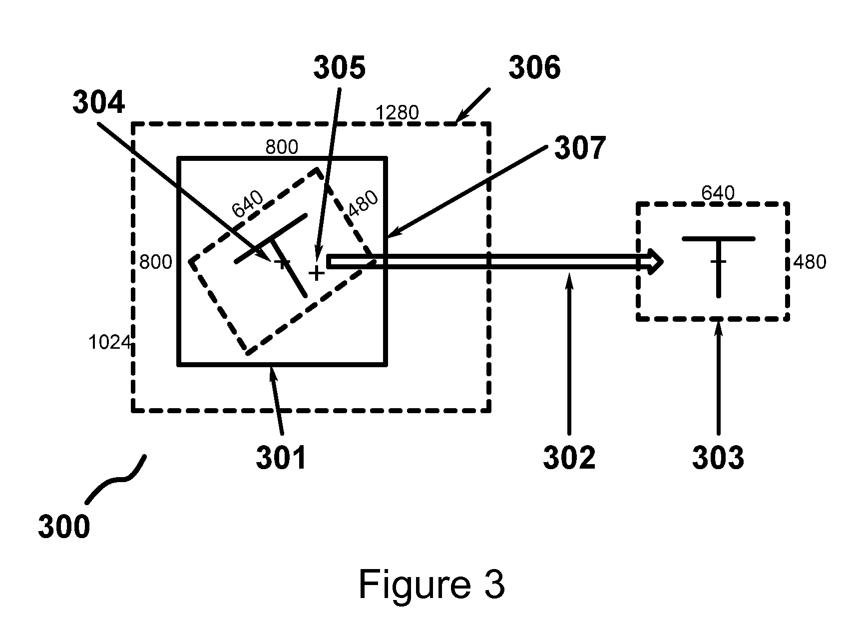
A system for emulating a continuous pan/tilt camera includes a camera having an image sensor for capturing an image. A camera orientation system includes a tip/tilt orientation mechanism having two axes of rotation with constrained range of movement for positioning the camera to capture the image within a hemispherical space. The two axes of rotation are generally orthogonal to each other and generally parallel to a plane forming a back side of the hemispheric space. An image transformation system rotates a portion of the captured image to emulate the continuous pan/tilt camera. The camera further includes a control system for adjusting an active area of the image sensor in response to a divergence between an optical center of the image sensor and a mechanical center of camera orientation system. The image transformation system is configurable in response to a spatial orientation of the hemispherical space.

Description

FEDERALLY SPONSORED RESEARCH OR DEVELOPMENT[0001]Not applicable.REFERENCE TO SEQUENCE LISTING, A TABLE, OR A COMPUTER LISTING APPENDIX[0002]Not applicable.COPYRIGHT NOTICE[0003]A portion of the disclosure of this patent document contains material that is subject to copyright protection. The copyright owner has no objection to the facsimile reproduction by anyone of the patent document or patent disclosure as it appears in the Patent and Trademark Office, patent file or records, but otherwise reserves all copyright rights whatsoever.FIELD OF THE INVENTION[0004]The present invention relates generally to cameras. More particularly, the invention relates to a camera comprising constrained-range hardware orientation means combined with an image rotation post-processing stage to emulate continuous pan / tilt cameras.BACKGROUND OF THE INVENTION[0005]Broadly speaking, there are two main categories of security camera: static (i.e. fixed or manually oriented) and dynamic (i.e., with powered ori...

Claims


Application Information

Patent Timeline
IPC IPC(8): H04N5/232
CPCG03B37/02H04N5/23203H04N5/2251H04N23/50H04N23/66H04N23/60G08B13/1963H04N7/18H04N23/69
Inventor PELLING, NICHOLAS JOHN
Owner PELLING NICHOLAS JOHN
Why Eureka
Try Eureka