Ct cone beam scanner

a cone beam and scanner technology, applied in the field of cone beam computerized tomography, can solve the problems of inability to accurately detect the position of the cone beam, etc., to achieve the effect of improving the temporal resolution

Active Publication Date: 2011-02-10
ARINETA
View PDF7 Cites 30 Cited by
  • Summary
  • Abstract
  • Description
  • Claims
  • Application Information

AI Technical Summary

Benefits of technology

[0014]An aspect of some embodiments of the present invention is the provision of system and method for providing a source trajectory that affords collecting a near complete or complete set volumetric data scanned with a cone beam CT scanner with improved temporal resolution. According to some embodiments of the present invention, complete set volumetric data is scanned during 360 degree scanning and a near complete set volumetric data is scanned during 180 degree scanning. According to some embodiments of the present invention, the trajectory is a non-circular trajectory that is a function of the angular rotation of the gantry. According to some embodiments of the present invention, the orientation of the beam is controlled so as to center the cone beam on the volume of interest along substantially the entire trajectory.

Problems solved by technology

Acquiring a 3D data set, one 2D slice at a time is inherently slow.
Moreover, in medical applications, motion artifacts occur because adjacent slices are not imaged simultaneously.
Also, dose utilization is less than optimal, because the distance between slices is typically less than an x-ray collimator aperture used to project the x-ray beam, resulting in double exposure to many parts of the inspected object.
One of the known drawbacks of cone beam CT scanning, as will be described in further detail below, is that the data set collected over a single scan is incomplete.
Missing data introduces artifacts during image reconstruction, resulting in images which may be inadequate for, for example, medical diagnosis or part quality determination purposes.

Method used


Image

  • Ct cone beam scanner
  • Ct cone beam scanner
  • Ct cone beam scanner

Examples


Embodiment Construction

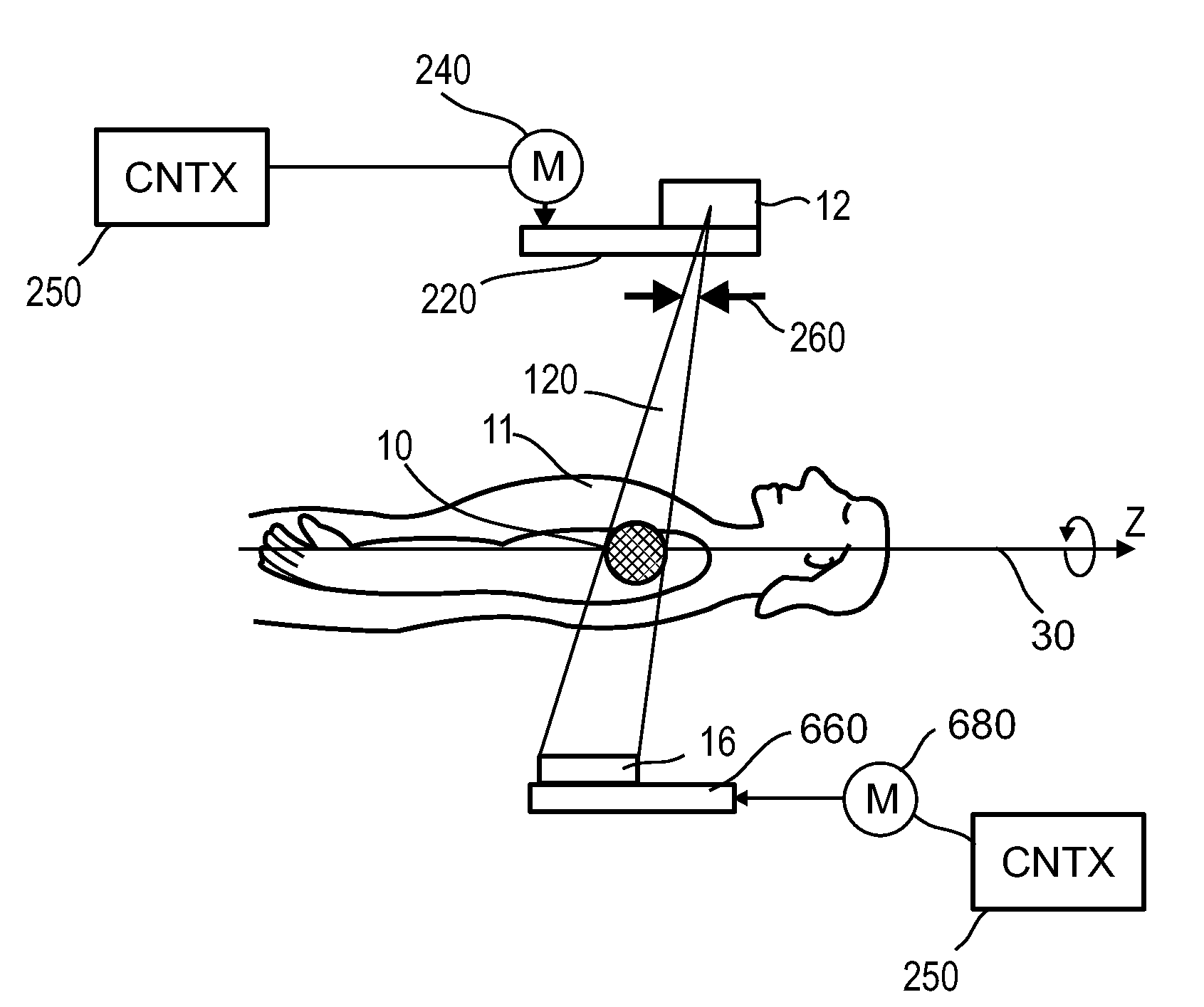
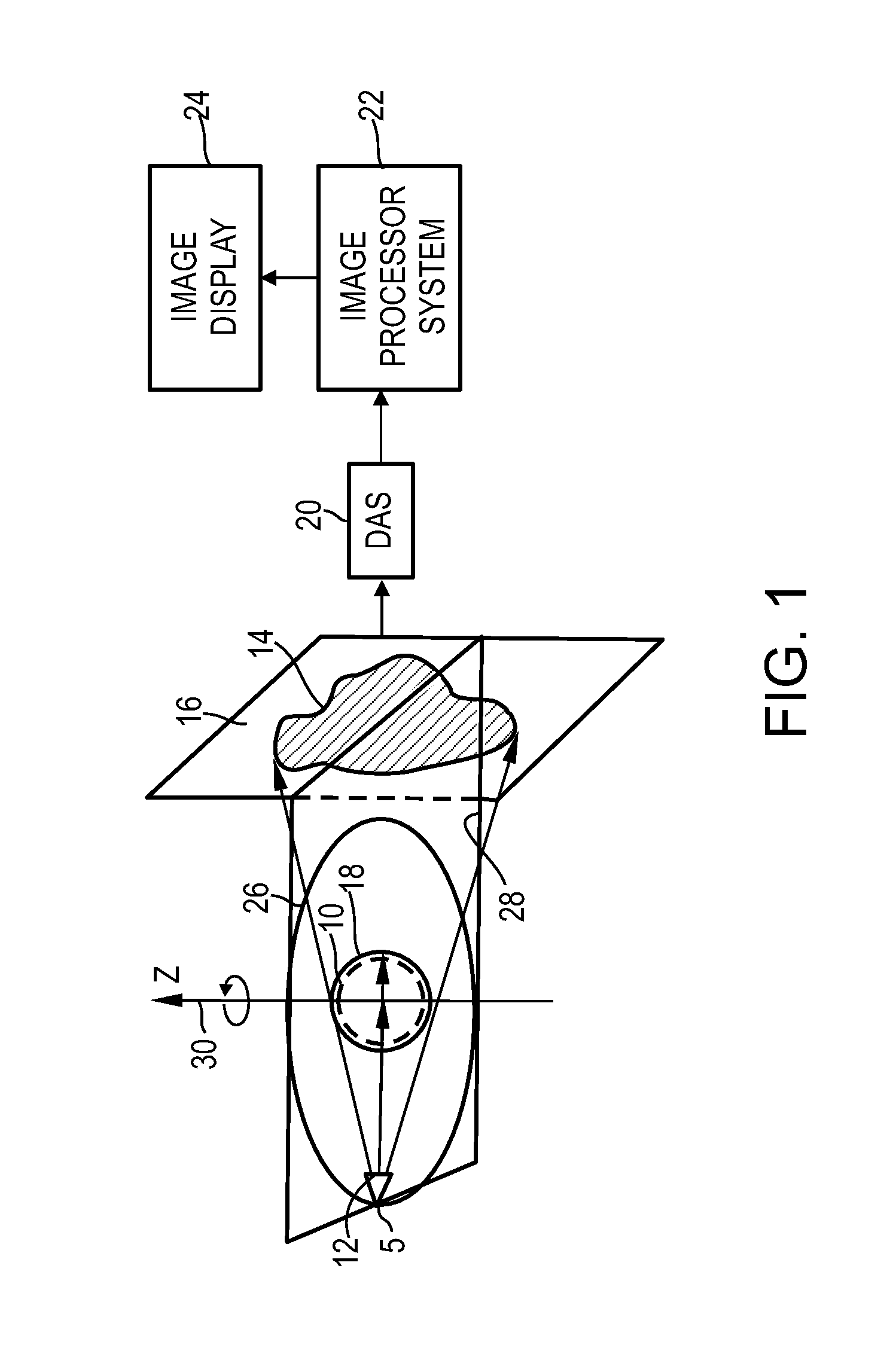
[0068]The present invention relates to cone beam Computerized Tomography (CT), and more particularly, but not exclusively, to cone beam CT for scanning moving objects.

[0069]A problem in conventional circular trajectory cone beam scanners is data incompleteness which typically leads to artifacts in image reconstruction. Data incompleteness occurs since there are planes through the reconstructed volume which are approximately parallel to the source trajectory and thereby do not intercept the source trajectory as is required by the Tuy-Smith condition.

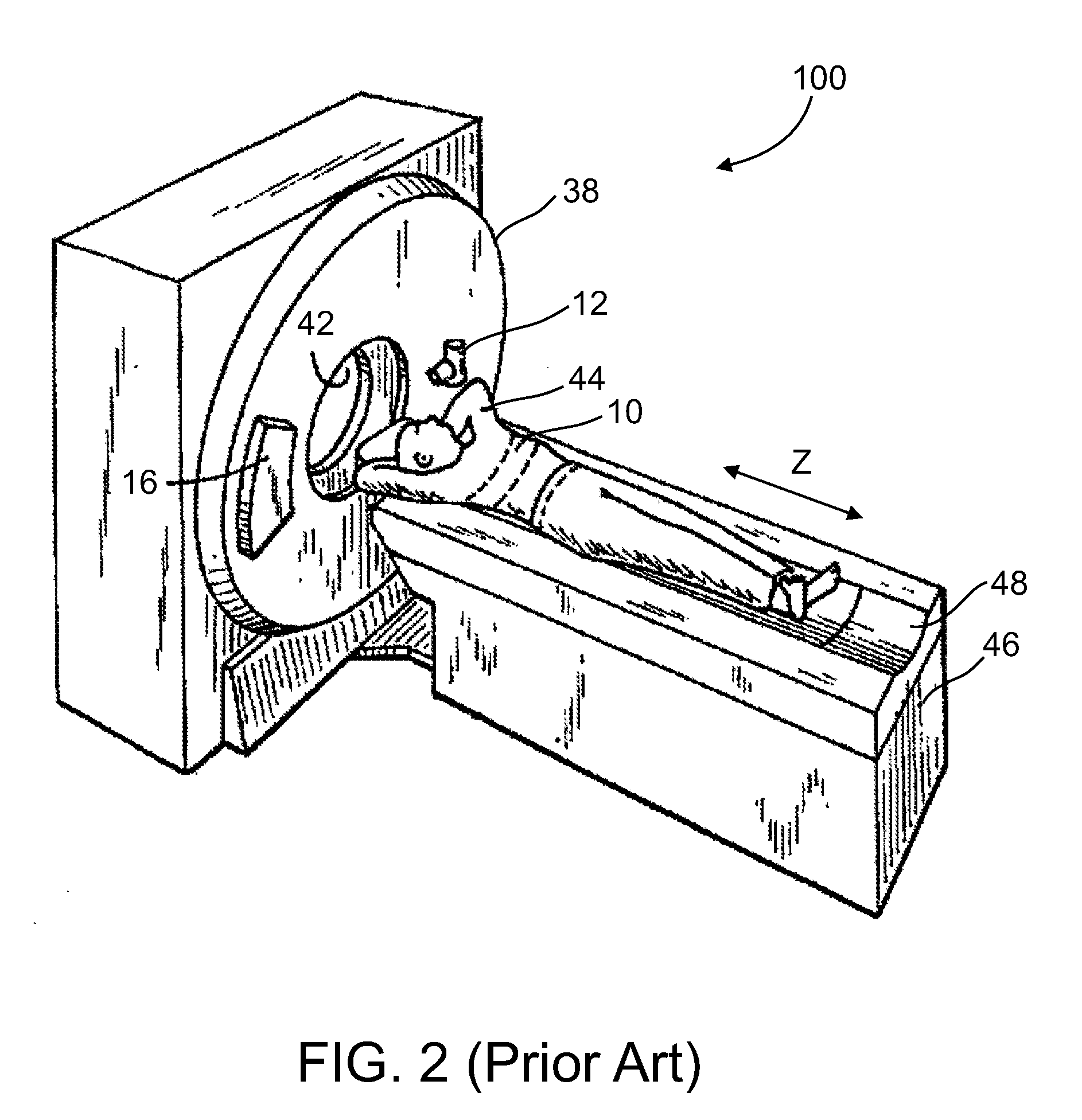
[0070]While helical (or spiral) scanning may provide for reduced data incompleteness for substantially large volumes, e.g. larger than a volume covered by a cone beam angle, this method has poor temporal resolution which is a disadvantage for some applications such as cardiac imaging where the heart is in motion. Another disadvantage when scanning relatively small volumes is that in helical scanning the beam covers different parts of the ...


PUM


Abstract

A CT scanner comprises at least one cone beam x-ray source assembly mounted on a gantry frame, the gantry frame rotatable about a rotation axis, the x-ray source assembly operable to emit a cone beam at an orientation with respect to the rotation axis, and a controller operable to adjust an orientation of the cone beam during a rotation cycle of the gantry, wherein the controller adjusts the orientation to radiate a substantially same volume of interest over the rotation cycle.

Description

FIELD OF THE INVENTION[0001]The present invention relates to cone beam Computerized Tomography (CT), and more particularly, but not exclusively, to cone beam CT applied to scan moving objects.BACKGROUND OF THE INVENTION[0002]CT scanners are used for medical imaging as well as for industrial inspection applications. CT imaging is based on an x-ray source mounted on a rotatable gantry opposite an x-ray detector array. The x-ray source directs an x-ray beam in a direction perpendicular to a rotational axis of the gantry through an object and toward the x-ray detector array as the gantry is rotated. The object is typically centered about the rotational axis of the gantry. The directed x-ray beam partially attenuated by the object impinges on the x-ray detector array to form an x-ray image of the object. Rotating the gantry provides for acquiring a plurality of angular views of the object. Typically an angular span of about 180 degree or more is used for imaging. In helical scanning, the...

Claims


Application Information

Patent Timeline
Patent Type & Authority Applications(United States)
IPC IPC(8): A61B6/03
CPCA61B6/032A61B6/027A61B6/4028
Inventor DAFNI, EHUDBRADA, RAFIRUIMI, DAVID
Owner ARINETA
Why Eureka
Try Eureka