
Drill bit

Inactive Publication Date: 2011-02-10
NIWA DAIYAMONDO INDS
View PDF15 Cites 0 Cited by
  • Summary
  • Abstract
  • Description
  • Claims
  • Application Information

AI Technical Summary

Benefits of technology

[0016]As described above, the drill bit according to one exemplary embodiment of the present invention may be useful to enable a continuous drilling operation on a high-strength workpiece.
[0017]Also, the drill bit according to one exemplary embodiment of the present invention may be useful to enable the refilling of a cutting oil that is used to suppress any increase in temperature through friction, which makes it possible to re-use the drill bit.
[0018]In addition, the drill bit according to one exemplary embodiment of the present invention may be useful to suppress the damage of drill bits to the maximum extent, the damage of drill bits being caused by heat of friction generated during the continuous drilling operation on a workpiece.
[0019]Additionally, the drill bit according to one exemplary embodiment of the present invention may be useful to shorten a time for the drilling operation on the high-strength workpiece.
[0020]Furthermore, the drill bit according to one exemplary embodiment of the present invention may be useful to drill the high-strength workpiece to the maximum extent using the minimum number of drill bits.

Problems solved by technology

However, conventional concrete drill bits do not have as much durability (i.e. strength) as high-strength construction materials to machine the high-strength construction materials.
Also, the conventional concrete drill bits generate heat through friction in the drilling of a workpiece.
As a result, the drill bits may easily get blunt and finally may not be used any more.
Owing to these above problems, several drill bits should be unavoidably used to drill one workpiece.
Also, a continuous drilling operation is impossible to be performed in order to reduce the damage of the drill bits by the generated heat of friction during the drilling operation using each drill bit.

Method used


Image

  • Drill bit
  • Drill bit
  • Drill bit

Examples


Embodiment Construction

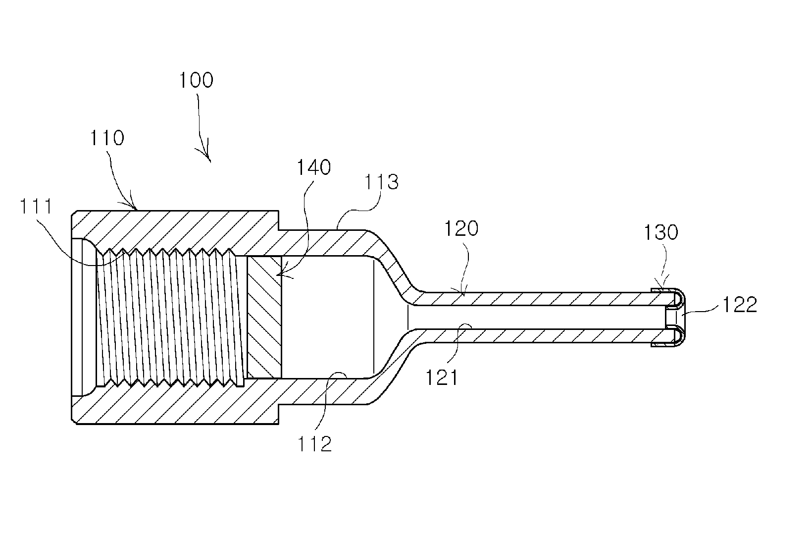
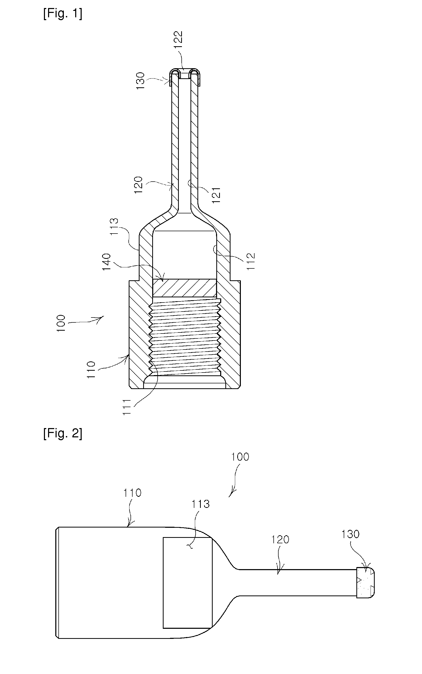
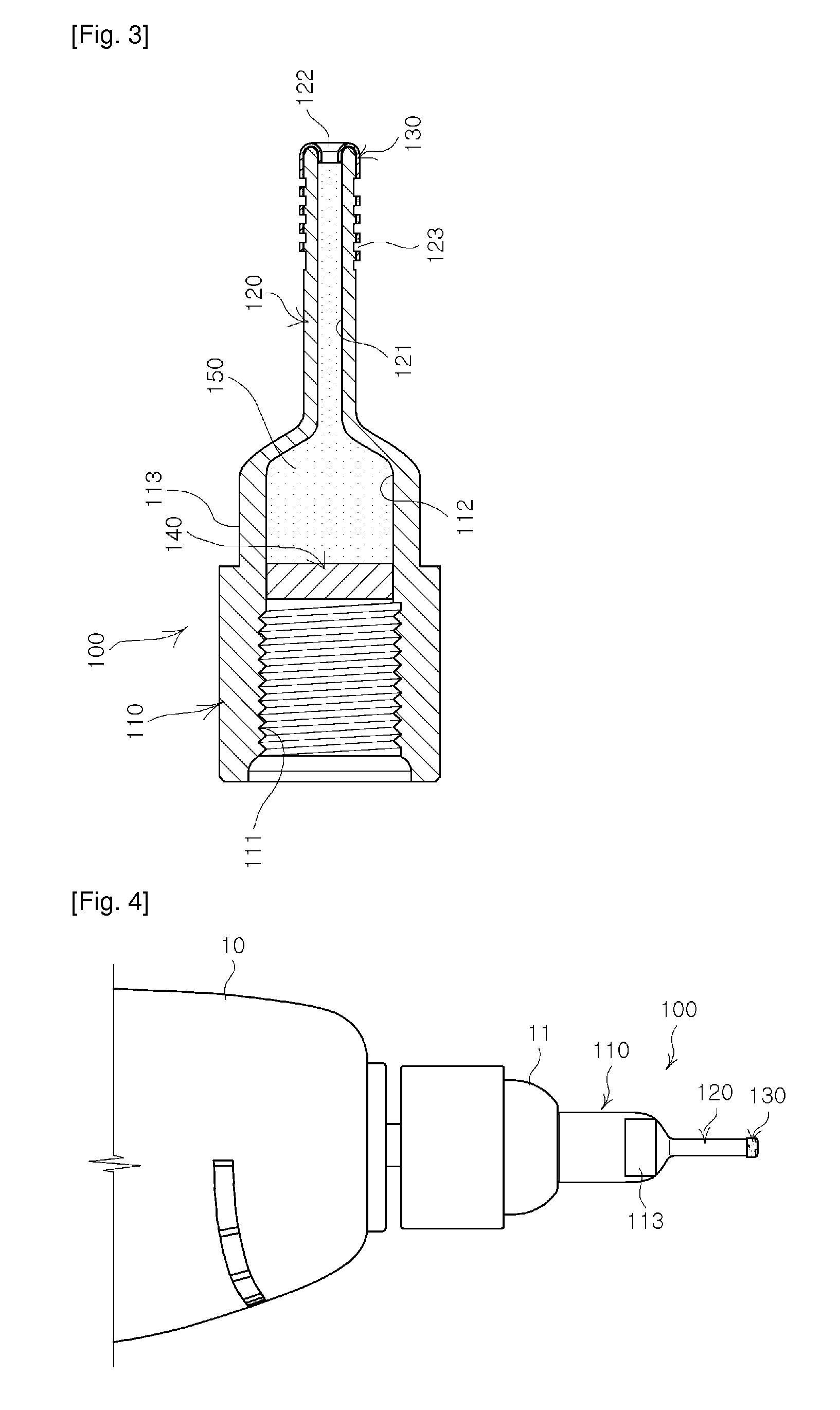
[0026]Hereinafter, a drill bit according to one exemplary embodiment of the present invention will be described in detail for better understandings of the above-mentioned characteristics of the present invention.

[0027]Hereinafter, the best exemplary embodiments of the present invention will be described in detail for the better understandings of the technical characteristics of the present invention, but the technical characteristics of the present invention are not particularly limited to the best exemplary embodiment, so it is considered that the present invention can be realized as the best exemplary embodiments.

[0028]Therefore, it should be understood that other equivalents and modifications could be made thereto without departing from the scope of the invention.

[0029]Furthermore, for reference numerals that are marked hereinafter in the accompanying drawings for better understanding of the exemplary embodiments of the present invention, parts and their related counterparts that...


PUM

PropertyMeasurementUnit
Strengthaaaaaaaaaa

Abstract

There is provided a drill bit capable of performing a continuous drilling operation on a high-strength workpiece such as a tempered tile and the like. The drill bit comprises a bit body having a receptor portion formed therein, the receptor portion being filled with a cutting oil; a drilling portion extended from one end of the bit body and coupled to the receptor portion of the bit body to form a channel in which a capillary phenomenon occurs, and having an opening formed in one end thereof; and a cutting portion provided in the opening of the drilling portion to drill a workpiece. The drill bit thus configured may be useful to enable a continuous drilling operation on the high-strength workpiece, to enable the refilling of a cutting oil used to cool the high-strength workpiece, to shorten a time for the drilling operation on the high-strength workpiece, and to drill the high-strength work-piece to the maximum extent using the minimum number of drill bits.

Description

TECHNICAL FIELD[0001]The present invention relates to a drill bit capable of performing a continuous drilling operation on a high-strength workpiece such as a tempered tile and the like.BACKGROUND ART[0002]In general, drill bits are used to form a hole in a workpiece. In particular, the drill bits used in the field of construction are divided into drill bits for forming a hole in a workpiece such as wood or metals; and drill bits for forming a hole in a workpiece such as concrete or stones.[0003]These drill bits have been used to form holes in construction materials such as installed tiles. Recently, tempered tiles made of high-strength materials, which have been used as flooring materials, are installed onto a wall structure of a bathroom, an interior space, or the like in order to offer designs of buildings and the like. Drilling operations should be performed to install necessary facility equipment such as electricity or lightings and a variety of products such as accessories for...

Claims


Application Information

Patent Timeline
IPC IPC(8): B23B51/06B23B51/02
CPCB23B51/06B23B2226/18B23B2226/315B23B2250/12B28D1/041B28D1/146Y10T408/455Y10T408/45Y10T408/895Y10T408/896Y10T408/907Y10T408/81B28D7/02B23B51/00B23B51/02B26F1/16
Inventor HONG, JAE-HYUNCHOI, JONG-SUKHONG, DO-UI
Owner NIWA DAIYAMONDO INDS
Learn More