Implant root for tooth implanting
a technology for implant root and tooth, which is applied in the field of implant root for tooth implanting, can solve the problems of limited fixing capability of implant root, inferior ability of bone growth, etc., and achieve the effects of increasing the space for bone growth in the denture base, increasing the area of roughened helical treated surfaces, and increasing the firmness of the implant root implanting into the denture bas
- Summary
- Abstract
- Description
- Claims
- Application Information
AI Technical Summary
Benefits of technology
Problems solved by technology
Method used
Image
Examples
first embodiment
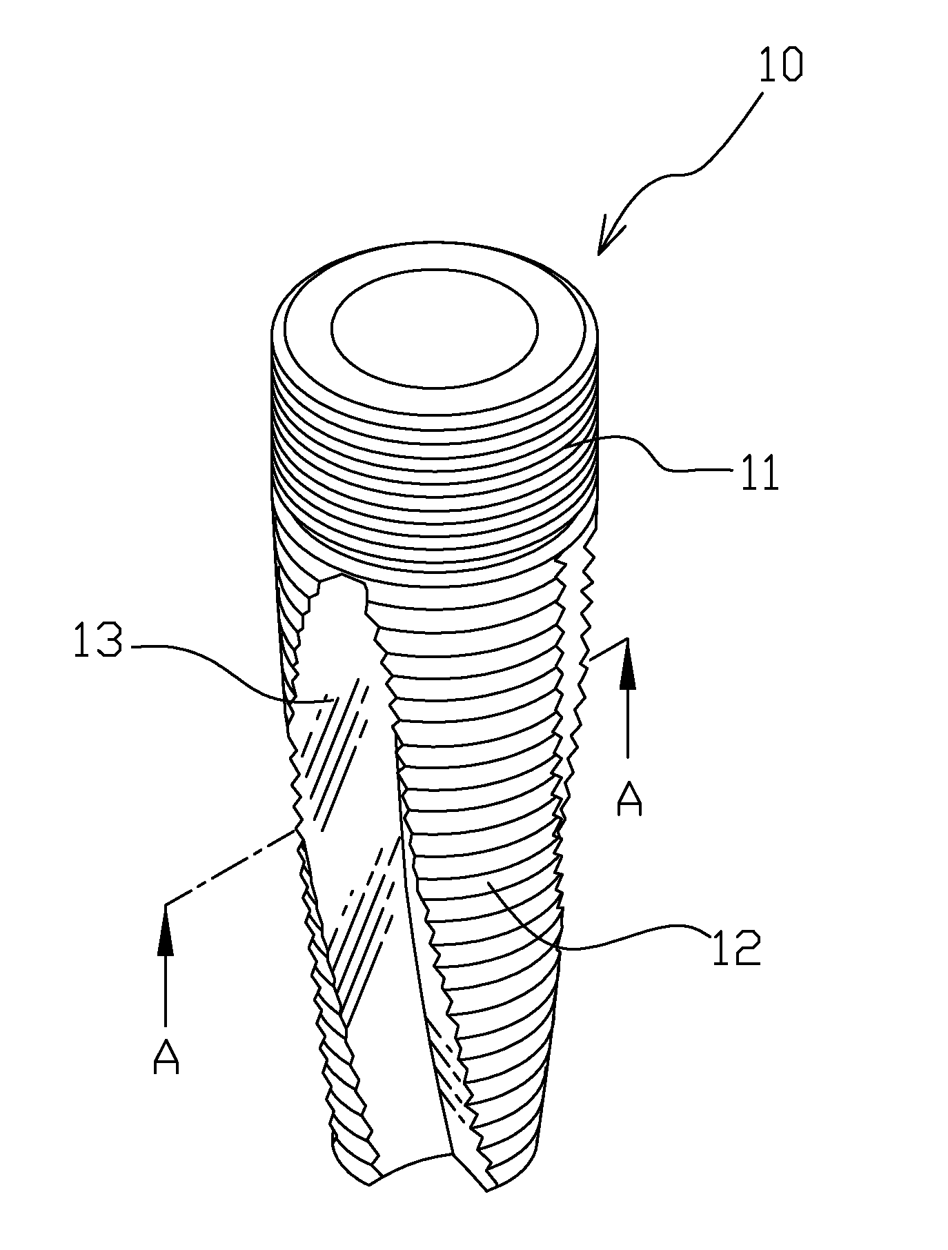
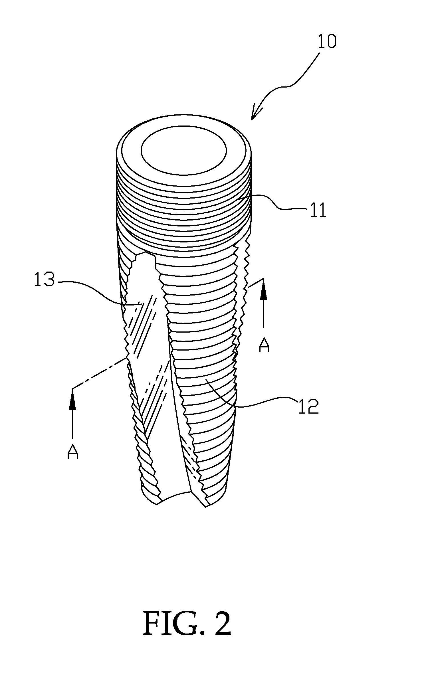
[0025]Referring to FIGS. 2 and 3 showing the present invention, wherein an implant root 10 has on its upper area a connecting portion 11, the connecting portion 11 has on its outer surface a fine threaded portion, and the implant root 10 has on its lower area a coarse threaded portion 12. The connecting portion 11 is connected with an abutment 6 of a crown such as is shown in FIG. 6; the surfaces of the coarse threaded portion 12 have sharp threads that can be implanted in a denture base of a patient by rotation.
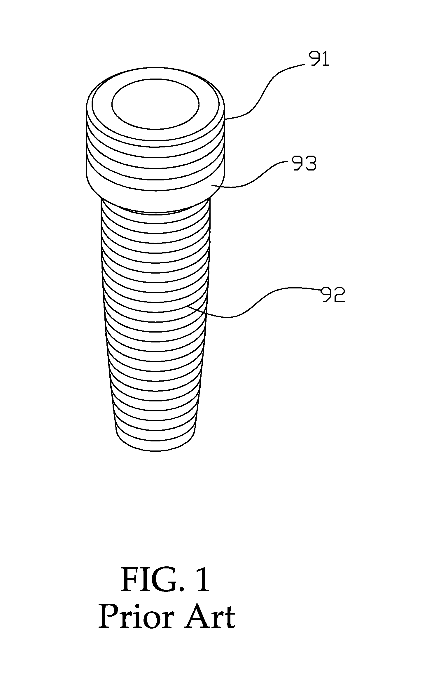
[0026]Two helical treated surfaces 13 (on which cut faces are plane surfaces) formed on the coarse threaded portion 12 extending in the vertical direction are treated with roughened coatings, for example, covered with hydroxyapatite coatings, and the helical treated surfaces 13 extend in the whole length of the coarse threaded portion. Thereby the areas of the roughened helical treated surfaces 13 are larger than the area of the conventional horizontal treated surface 93, an...
second embodiment
[0027]Referring to FIGS. 4 and 5 showing the present invention, wherein an implant root 20 has a connecting portion 21, the connecting portion 21 has on its outer surface a fine threaded portion, and the implant root 20 has on its lower area a coarse threaded portion 22. The coarse threaded portion 22 has three helical treated surfaces 23 laid out in an equiangularly spaced away mode and all extending in the vertical direction and are treated with HA coatings, cut faces on the three helical treated surfaces 23 are recessed arciform surfaces (referring to FIG. 5) to further increase the areas of the treated surfaces and the space for staying of the bone dusts.
[0028]Referring to FIGS. 6 and 7, the connecting portion 11 is provided with a polygonal hole 14, a screw hole 15 is provided in the bottom surface of the polygonal hole 14. Wherein the polygonal shape of the polygonal hole 14 is mated with the shape of a connecting section 61 of the abutment 6, so that the abutment 6 can be fas...
third embodiment
[0029]Referring to FIGS. 8 and 9 showing the present invention, wherein an implant root 30 has a connecting portion 31, the connecting portion 31 has on its outer surface a fine threaded portion, and the implant root 30 has on its lower area a coarse threaded portion 32. The coarse threaded portion 32 has three helical treated surfaces 33 laid out in an equiangularly spaced away mode. The three helical treated surfaces 33 on which cut faces are helical surfaces (referring to FIG. 9) all extend from bottom to top in the vertical direction on the coarse threaded portion 32, and in the whole length of the coarse threaded portion 32 till the fine threaded portion of the connecting portion 31, and are cut inwardly gradually shallower from bottom to top in order to avoid being cut into the central positioning hole.
[0030]Referring to FIG. 9, the helical treated surfaces 33 are treated with roughened coatings; wherein each of many cut faces 33a on the helical treated surfaces 33 at correspo...
PUM
 Abstract
Description
Claims
Application Information
 - R&D
- Intellectual Property
- Life Sciences
- Materials
- Tech Scout
- Unparalleled Data Quality
- Higher Quality Content
- 60% Fewer Hallucinations
Browse by: Latest US Patents, China's latest patents, Technical Efficacy Thesaurus, Application Domain, Technology Topic, Popular Technical Reports.
© 2025 PatSnap. All rights reserved.Legal|Privacy policy|Modern Slavery Act Transparency Statement|Sitemap|About US| Contact US: help@patsnap.com


