Wireless technology as a data conduit in three-dimensional ultrasonogray

a three-dimensional ultrasonogray and data conduit technology, applied in the field of medical imaging systems, can solve the problems of increasing the cost of medical imaging equipment shipping from developed nations into lesser-developed nations, requiring trained operators to use, and updating, so as to reduce the cost of imaging, improve the accuracy of diagnosis, and increase the cost of health technology

Inactive Publication Date: 2011-02-10
RGT UNIV OF CALIFORNIA
View PDF14 Cites 107 Cited by
  • Summary
  • Abstract
  • Description
  • Claims
  • Application Information

AI Technical Summary

Benefits of technology

[0014]The present invention may also operate on a cellular phone that can send and receive pictures, or audio and video clips. In addition, a centralized database can be maintained in the data processing facility. This database may be compatible with all imaging modes and may be used to track specific patients or to compare images from one patient to another. In other embodiments, the cellular phone transmits data to the central image processing facility, but does not receive information, data, or images back from the facility. Rather, trained operators and medical professionals at the central data processing facility, or another location may perform the diagnosis, or collect the data, without displaying an image on the phone screen for the patient to view. Thus, once processed at the central image processing facility, a diagnostic image(s) or other processed data can be sent anywhere necessary by various means such as phone or Internet.
[0015]In further embodiments, the present invention need not be limited to imaging systems at all, but may be used in other contexts as well. For example, in some aspects, the cellular phone is simply used as a data conduit between any two devices to replace hard wiring such that the cellular phone is a “middle node” of a system (thus permitting component devices of the system to be positioned at various locations). This optional embodiment is in contrast to existing communication systems in which cellular phones operate as the end node of the system. Thus, the present invention also provides a system of transferring data between parts of a complex device using cellular phone communication protocols, comprising: a first system component of a complex device; a second system component of a complex device; and a cellular phone-type device, wherein raw data is sent through the cellular phone-type device from the first system component to the second system component of the complex device.
[0016]In another alternative embodiment, there is provided an imaging system, centered on wireless technology and cloud computing, which is designed to overcome the problems of increasing health technology costs. For example, provided is a wireless, distributed network, and central (cloud) computing enabled three-dimensional (3-D) ultrasound system. Specifically, a 3-D high-end ultrasound scan is produced at a central computing facility using raw data acquired at a remote patient site with an inexpensive low-end ultrasound transducer designed for two-dimensional (2-D) imaging. Such system uses a mobile device and a wireless connection link to transmit raw data from the patient site to the central computing facility. Producing high-end 3-D ultrasound images with simple low-end transducers significantly reduces the cost of imaging and removes the requirement of having a highly trained imaging expert at the patient site. Specifically, the need for hand-eye coordination and the ability to reconstruct a 3-D mental image from 2-D scans, which requires a highly trained physician for the operation of the system, is eliminated. As such, relatively untrained medical workers, particularly in developing nations or at remote accident sites or battlefield, can administer imaging and provide a more accurate diagnosis.
[0017]FIG. 1 is an illustration of the operation of the present invention (for a patient self-screening for breast cancer tumors).
[0018]FIG. 2 is a schematic representation of a frequency-division multiplexing electrical impedance tomography technique performed by a data acquisition device in accordance with the present invention.
[0019]FIG. 3 is an illustration of an exemplary architecture of a data acquisition device that can be used in accordance with the present invention.

Problems solved by technology

However, current medical imaging systems are expensive, and require trained operators to use, update, and to repair.
In addition, the costs of shipping medical imaging equipment from developed nations into lesser-developed nations can also be prohibitive, and resources may not be available to operate the equipment when it arrives.
Moreover, a large part of the costs of conventional medical imaging systems are due to the fact that they are self-contained units that combine data-acquisition hardware with software-processing hardware in one device.
As a result, much of the world's population lacks access to standard medical imaging systems such as ultrasounds, X-rays, and other imaging devices.

Method used


Image

  • Wireless technology as a data conduit in three-dimensional ultrasonogray
  • Wireless technology as a data conduit in three-dimensional ultrasonogray
  • Wireless technology as a data conduit in three-dimensional ultrasonogray

Examples


Embodiment Construction

(a) Medical Imaging Systems:

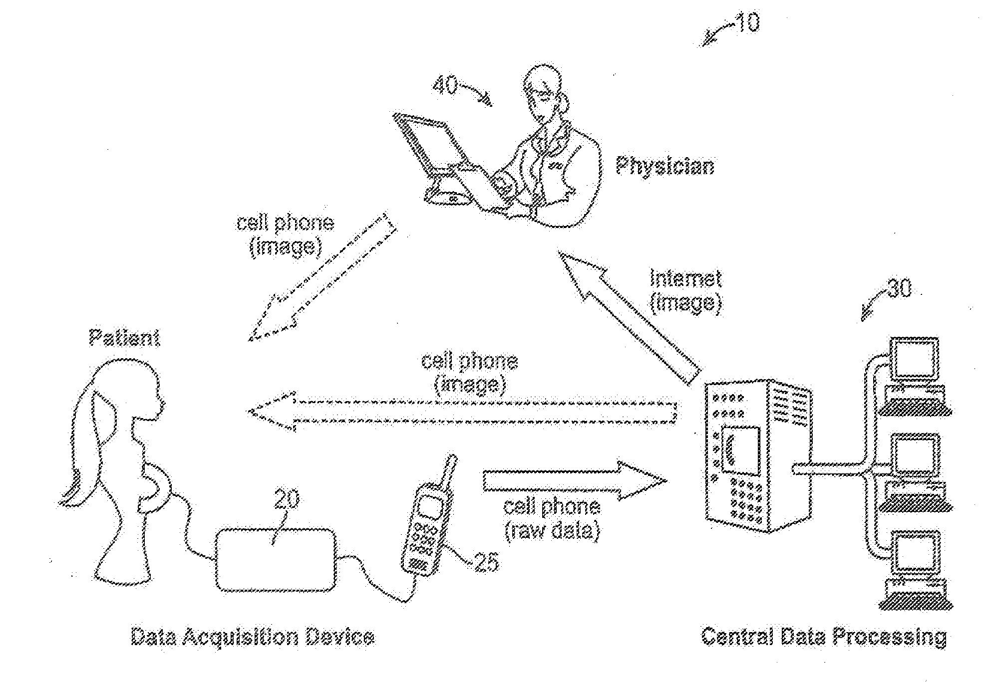
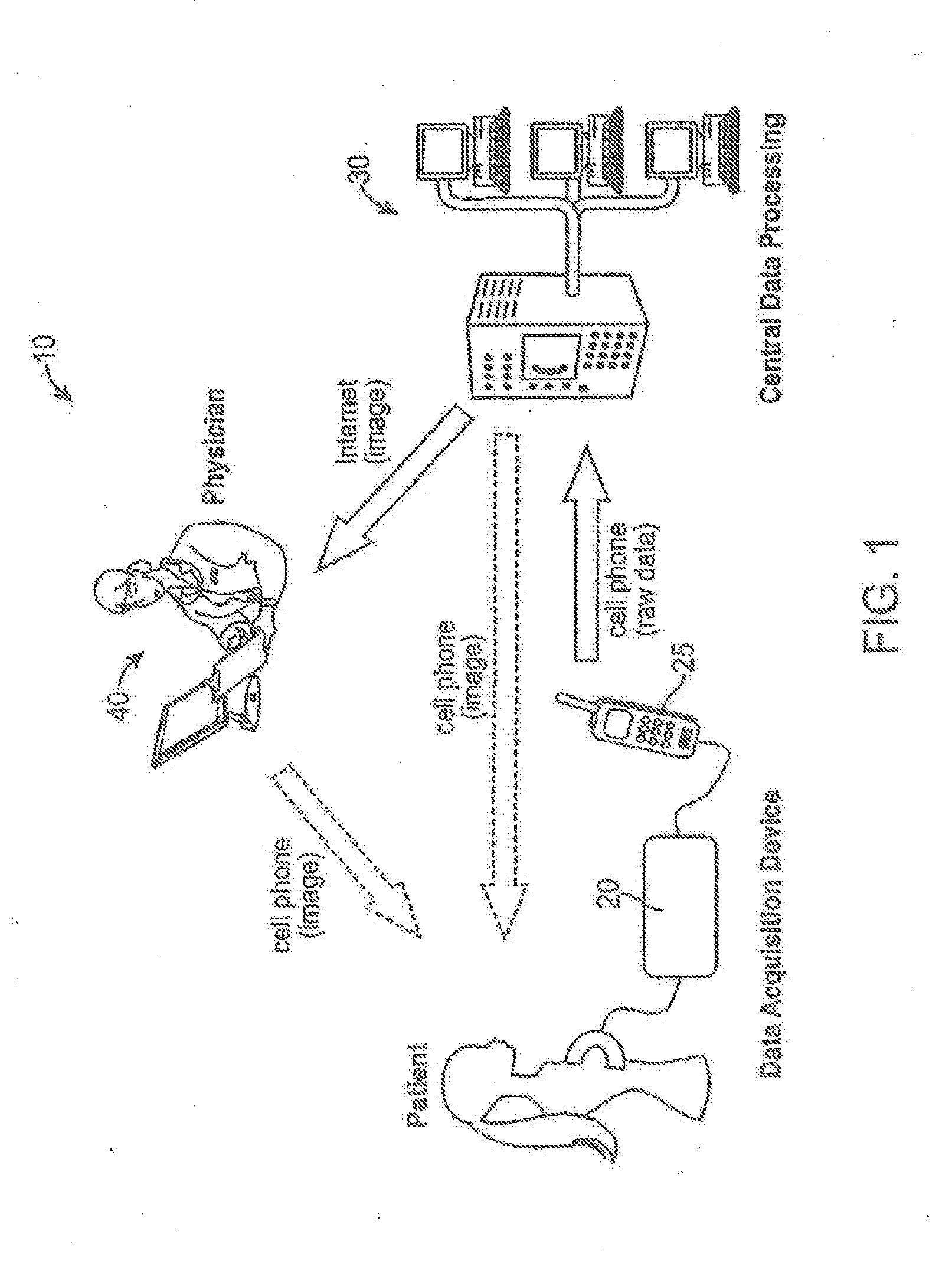
[0033]In accordance with the present invention, a conventional cellular phone is used as an integral and enabling component of a spatially dispersed medical imaging system.

[0034]In one embodiment, the cellular phone and a data gathering device are used at a patient site, with the cellular phone communicating with a multi-server processing center (possibly in a completely different part of the world). The multi-server processing center simultaneously serves many patient data gathering devices in the field. The multi-server processing center thus acts as a central image reconstruction and data processing facility.

[0035]Specifically, the cellular phone at the patient site transfers the raw data to an image reconstruction and data processing facility which then returns a reconstructed image through the cellular phone. The cellular phone is also used to display the image and for some local processing at the patient site. As will be explained, the fact that the...


PUM


Abstract

An imaging system, having: an imaging data acquisition device; a remote image reconstruction and data processing facility; and a wireless data transfer to transmit raw data from the data acquisition device to the remote facility. At the facility, the raw data is processed to prepare a diagnostic image that can be transmitted to an expert or non-expert, or transmitted back to the display of the wireless data transfer device.

Description

CROSS REFERENCE TO RELATED APPLICATIONS[0001]This application is a continuation-in-part of U.S. patent application Ser. No. 12 / 664,866, filed on May 21, 2010; which is a national stage entry of PCT / US2008 / 007605, filed on Jun. 17, 2008; which claims priority from U.S. Provisional Application No. 60 / 936,063, filed on Jun. 18, 2007; all of which are herein incorporated by reference in their entirety.[0002]This application also claims priority from U.S. Provisional Application No. 61 / 234,609, filed on Aug. 17, 2009; U.S. Provisional Application No. 61 / 239,644, filed on Sep. 3, 2009; and U.S. Provisional Application No. 61 / 254,941, filed on Oct. 26, 2009; all of which are herein incorporated by reference in their entirety.STATEMENT REGARDING FEDERALLY-SPONSORED RESEARCH AND DEVELOPMENT[0003]This invention was made with government support under NIH Grant No. R01 RR018961 awarded by the U.S. National Institutes of Health. The U.S. Government has certain rights in this invention.BACKGROUND...

Claims


Application Information

Patent Timeline
Patent Type & Authority Applications(United States)
IPC IPC(8): H04W4/00G06K9/00G16H30/20G16H40/67
CPCG06F19/321H04W88/02G06F19/3418G16H30/20G16H40/67
Inventor RUBINSKY, BORISIVORRA, ANTONIGRANOT, YAIRMEIR, ARIE
Owner RGT UNIV OF CALIFORNIA
Why Eureka
Try Eureka