
Implantable electrode array assembly including a carrier for supporting the electrodes and control modules for regulating operation of the electrodes embedded in the carrier, and method of making same

Active Publication Date: 2011-02-10
STRYKER CORP
View PDF6 Cites 52 Cited by
  • Summary
  • Abstract
  • Description
  • Claims
  • Application Information

AI Technical Summary

Benefits of technology

[0011]This invention is related to a new and useful electrode array designed for implantation into a living being. The electrode array of this invention includes one or more control modules that are built into the array so as to minimize the extent to which the conductors that extend to the module / modules are subjected to breakage-inducing stress.
[0012]The electrode array of this invention includes a carrier. Typically the carrier is formed out of material that is at least flexible so that the carrier at least conforms to the tissue against which the array is deployed. Often the carrier is formed from material that, in addition to being flexible, has some degree of elasticity. This allows the electrode array assembly to be deployed using minimally invasive surgical techniques.
[0015]The vias and conductors of the electrode array of this invention are primarily disposed on or extend through layers of material that has some degree of flexibility. The vias themselves are relatively short in length. The conductors to which the vias extend are thin both in their height and width. These dimensional features of the vias and on-array conductors improve their flexibility. Collectively, the flexibility of these components, the insulating material, the vias and the conductors, reduces the extent to which the mechanical stress to which the vias and conductors are exposed can cause their breakage.

Problems solved by technology

In contrast to an electrode array with a smaller number of electrodes, use of the above-described array increases the likelihood that the current flow can be set to provide desired therapeutic effects, with tolerable side effects.
Physical constraints make it difficult to implant large numbers of conductors in the patient.
Accordingly around the perimeter of the package, where the conductors are stopped from flexing, the conductors may be subjected to considerable stress.
There is a concern that this stress could induce failure in the conductors.
These wire bonds, given the fragility of the wires from which they are formed, may also be prone to breakage.
Over time, the vibration induced by this movement can potentially cause these wire bonds to fracture.
Clearly, the failure of these wire bonds, or complementary conductors can result in malfunction of electrode array.

Method used


Image

  • Implantable electrode array assembly including a carrier for supporting the electrodes and control modules for regulating operation of the electrodes embedded in the carrier, and method of making same
  • Implantable electrode array assembly including a carrier for supporting the electrodes and control modules for regulating operation of the electrodes embedded in the carrier, and method of making same
  • Implantable electrode array assembly including a carrier for supporting the electrodes and control modules for regulating operation of the electrodes embedded in the carrier, and method of making same

Examples


Embodiment Construction

I. Electrode Array Assembly

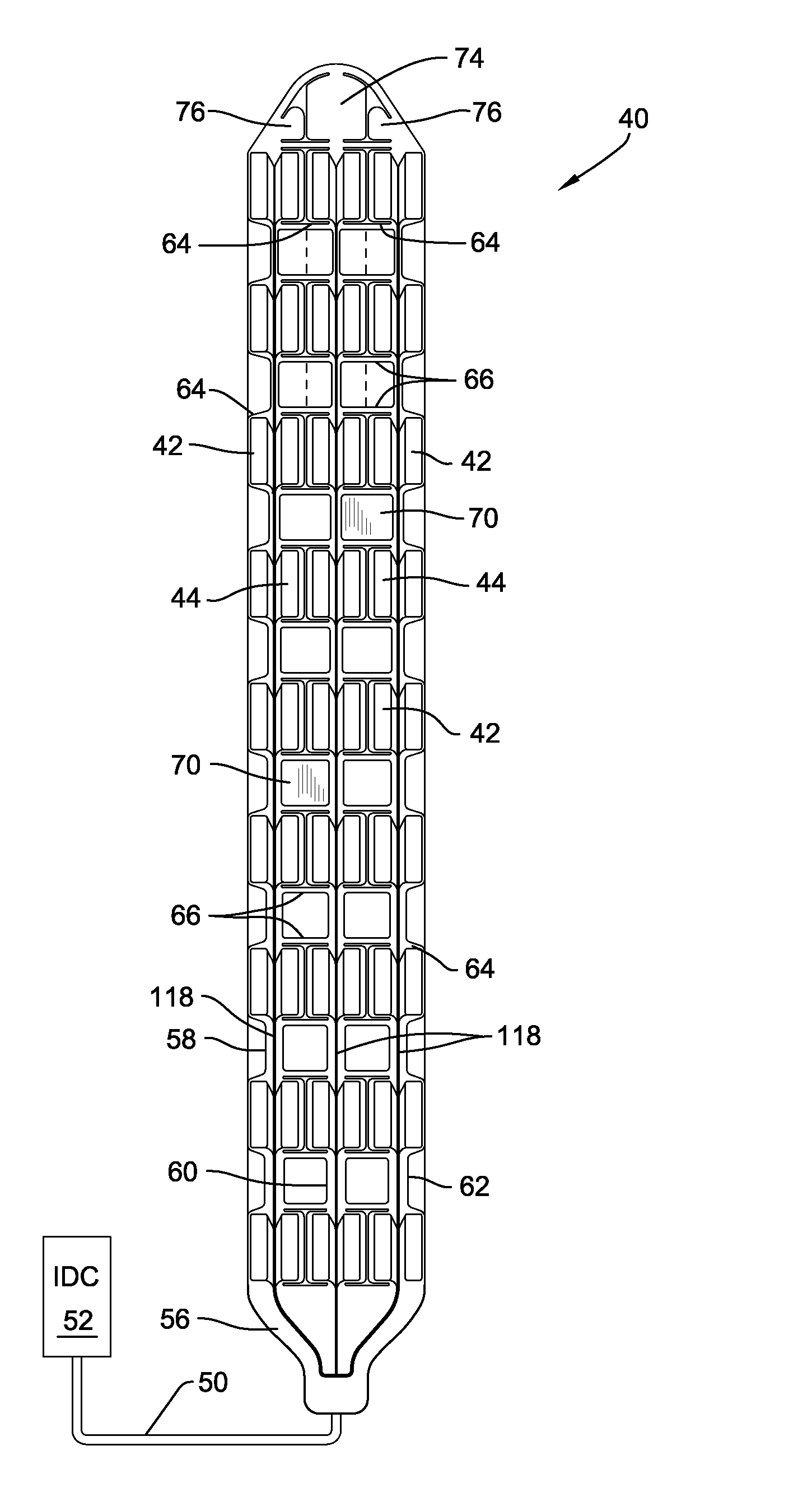
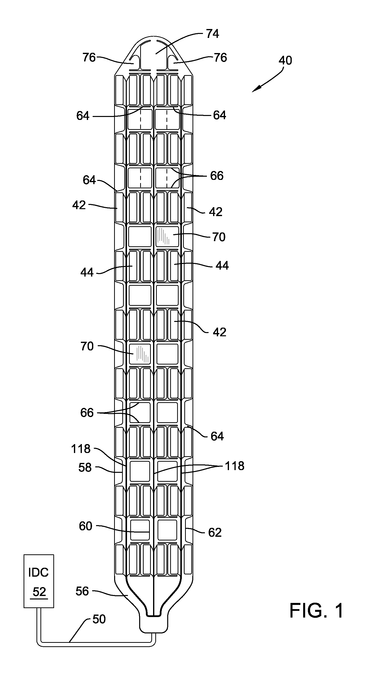
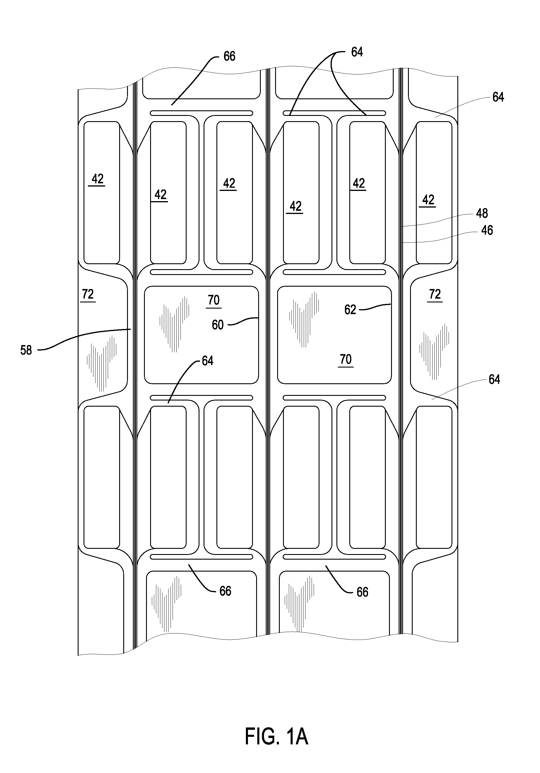
[0037]FIGS. 1, 1A and 2 illustrate an electrode array 40 of this invention. Electrode array 40 includes a number of individual electrodes 42 depicted in outline as a number of rectangles in FIGS. 1 and 1A. Associated with each electrode 42 is a control module 44. Each control module 44 is an application specific integrated circuit (ASIC) that includes components able to source current from / sink current to the associated electrode 42. Conductors 46 and 48 extend from the control modules 44. Conductors 46 and 48 are connected to a cable 50 that extends from the proximal end of the electrode array assembly 40. Not illustrated are the individual conductors internal to cable 50. Cable 50 is connected to an implantable device controller (IDC) 52. The IDC contains the power source for the currents that are flowed between the electrodes 42. IDC 52 also contains a controller that generates the instructions that indicate between which electrodes 42 the currents are ...


PUM

PropertyMeasurementUnit
Timeaaaaaaaaaa
Electrical conductivityaaaaaaaaaa
Flexibilityaaaaaaaaaa

Abstract

An implantable electrode array that includes multiple spaced apart electrodes to which current can be individually sourced and sunk. The array includes a carrier that supports the electrodes. One or more control modules that source current to or sink current from the electrodes are disposed in recesses within the carrier. A sheet of material more flexible than the carrier is disposed between, on one side, the carrier and the control modules and, on the other side, the electrodes. Conductors over which instructions and power are applied to the control modules and conductors that extend between the control modules are the electrodes are embedded in and extend through the sheet of flexible material.

Description

FIELD OF THE INVENTION[0001]This invention relates generally to an implantable electrode array assembly and, more particularly, to an implantable electrode array assembly with one or more control modules for regulating the operation of the assembly embedded in the carrier that supports the electrodes.FIELD OF THE INVENTION[0002]There are a number of medical conditions for which it has been found that an effective therapy involves driving current through a section of the tissue of a patient. Often, the current is driven between the electrodes of an electrode array implanted in the patient. Generally, the electrode array includes a non-conductive carrier on which typically two or more electrodes are disposed. Once the electrode array is implanted, current is driven from at least one of the electrodes, through the adjacent tissue, to at least one of the other electrodes. The current flow through the tissue influences the tissue to accomplish a desired therapeutic result. For example, a...

Claims


Application Information

Patent Timeline
IPC IPC(8): A61N1/05H05K3/30
CPCH01L2924/01079A61N1/0553H01L24/24H01L2924/09701H01L2924/01006A61N1/05H01L2924/01075H01L2924/15165H01L2924/01023H01L2924/15153H01L2924/01077H05K1/185H01L2924/01005H01L2924/01078H01L2924/01082H01L2224/04105H01L2924/014H01L2224/20H01L2924/01033Y10T29/4913H01L2224/24227H01L2924/14H01L2924/00
Inventor JANIK, JOHNBRINDLEY, ROBKATRAGADDA, RAKESH BABUTANG, EDWARD CHIA-NING
Owner STRYKER CORP
Learn More