
Mechanical command to arm fuze

a technology of fuzes and mechanical components, applied in the field of command to arm fuzes, can solve the problems of sad will arm much too quickly, unrestrained arming time, and inability of gunners to rely on the effectiveness of fired ammunition

Active Publication Date: 2011-02-17
AMTEC CORP
View PDF4 Cites 9 Cited by
  • Summary
  • Abstract
  • Description
  • Claims
  • Application Information

AI Technical Summary

Benefits of technology

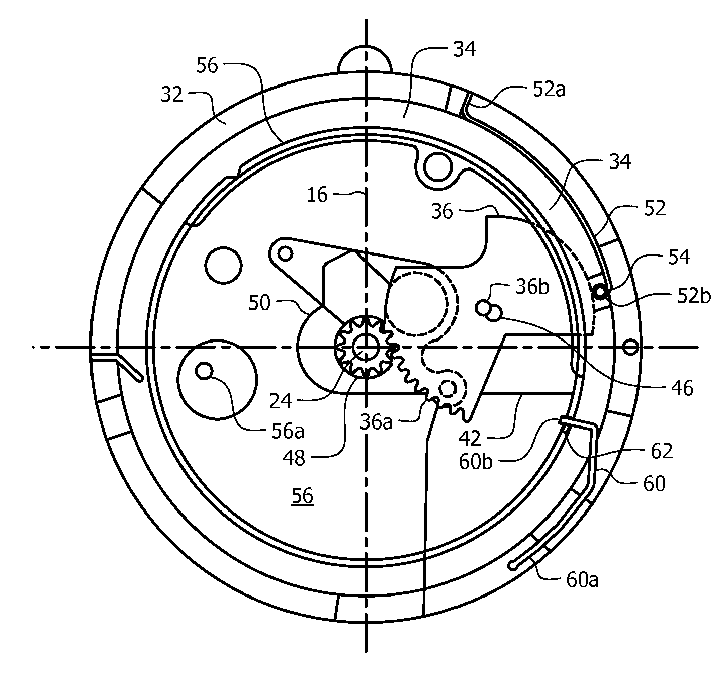
[0022]A first spring prevents the flywheel from rotating when centrifugal forces acting on the first spring are below a preselected threshold and a second spring holds the zip rotor in its safe position of repose even when the centrifugal forces are great enough to cause the first spring to disengage. The first spring has a first end permanently secured to a cylindrical sidewall of the upper housing and the first spring has a second end releasably secured to the flywheel. The first spring could also engage the timing post. The first spring is biased radially inwardly and the bias is overcome when centrifugal forces acting on the first spring exceed the predetermined threshold so that the flywheel is free to rotate about the firing pin.
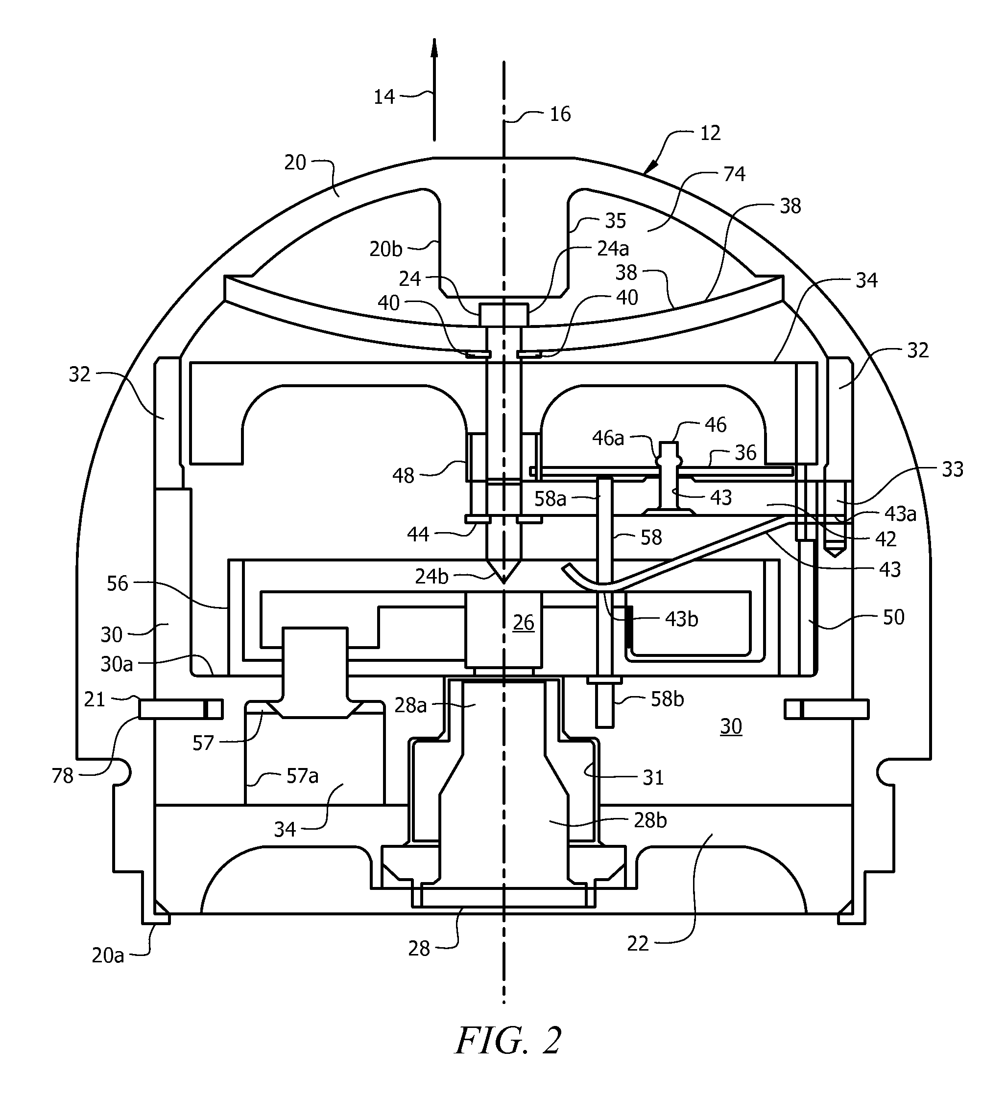
[0032]An anti-creep spring has a first, radially outermost end secured to the mounting pin and a second, radially innermost end disposed in abutting relation to the zip rotor. A rotor shaft aperture is formed in the second end of the anti-creep spring so that the rotor shaft extends through the rotor shaft aperture. When the hollow housing impacts against a soft target and the hollow housing is not deformed by the impact, the actuator is not driven into the firing pin. The zip rotor in its armed position slides along the rotor shaft in the direction of hollow housing travel due to the sudden deceleration of the hollow housing caused by the soft target impact. The zip rotor overcomes the bias of the anti-creep spring and the detonator carried by the zip rotor impacts against the firing pin.
[0034]A setback e-ring is disposed in encircling relation to the hollow housing and the lower housing. A first groove is formed in a peripheral vertical wall of the hollow housing and accommodates a radially outward edge of the setback e-ring. A second groove is formed in a peripheral vertical wall of the lower housing for accommodating a radially inward edge of the setback e-ring. The setback e-ring prevents relative movement between the hollow housing and the lower housing.
[0036]A bore is formed in a trailing side of said zip rotor and a recess is formed in the base plate. A setback pin having a head and a reduced diameter post is disposed in the recess and the reduced diameter post is disposed in the bore. A bias means holds the reduced diameter post of the setback pin in the recess. The setback pin maintains the zip rotor in the safe position of repose until acceleration forces acting on the round / projectile as it is launched from a weapon overcome the bias of the bias means and causes the reduced diameter post to withdraw from the recess and thereby unlock the zip rotor so that the zip rotor is free to rotate about the zip rotor shaft when said zip rotor is also released by the second spring.

Problems solved by technology

In this case, the gunner cannot rely on the effectiveness of fired ammunition because some of the rounds will not have armed when they hit the intended target.
This unrestrained arming time is due to the centrifugal force resulting from the mass of the rotor and detonator.
Therefore, unless the rotor is somehow slowed down, the SAD will arm much too quickly.
Friction between the various mechanical components of the SAD also absorbs much of the energy of the rotor.
Unfortunately, friction is not easy to characterize due to its variability in different environments; the coefficient of friction between two materials can vary by as much as 100% over a small temperature range.
Accordingly, small variations in tolerances can result in large variations in the amount of friction.
This friction problem cannot be easily addressed by adding lubrication to the system.
In fact, adding conventional lubrications such as oil can actually cause the SAD to bind and stop functioning.
The only practical means of lubricating the SAD is by the use of small, precise amounts of dry Teflon® powder; however, the powder application method must be tightly controlled or the treated SAD's may bind and not function.
Electronic SAD's have been developed, but they are not yet used in mass quantity production.
Battery shelf life has also been a concern that has yet to be adequately addressed.
The largest impediment for electronic fuze acceptance remains the cost of production in large quantities.

Method used


Image

  • Mechanical command to arm fuze
  • Mechanical command to arm fuze
  • Mechanical command to arm fuze

Examples


Embodiment Construction

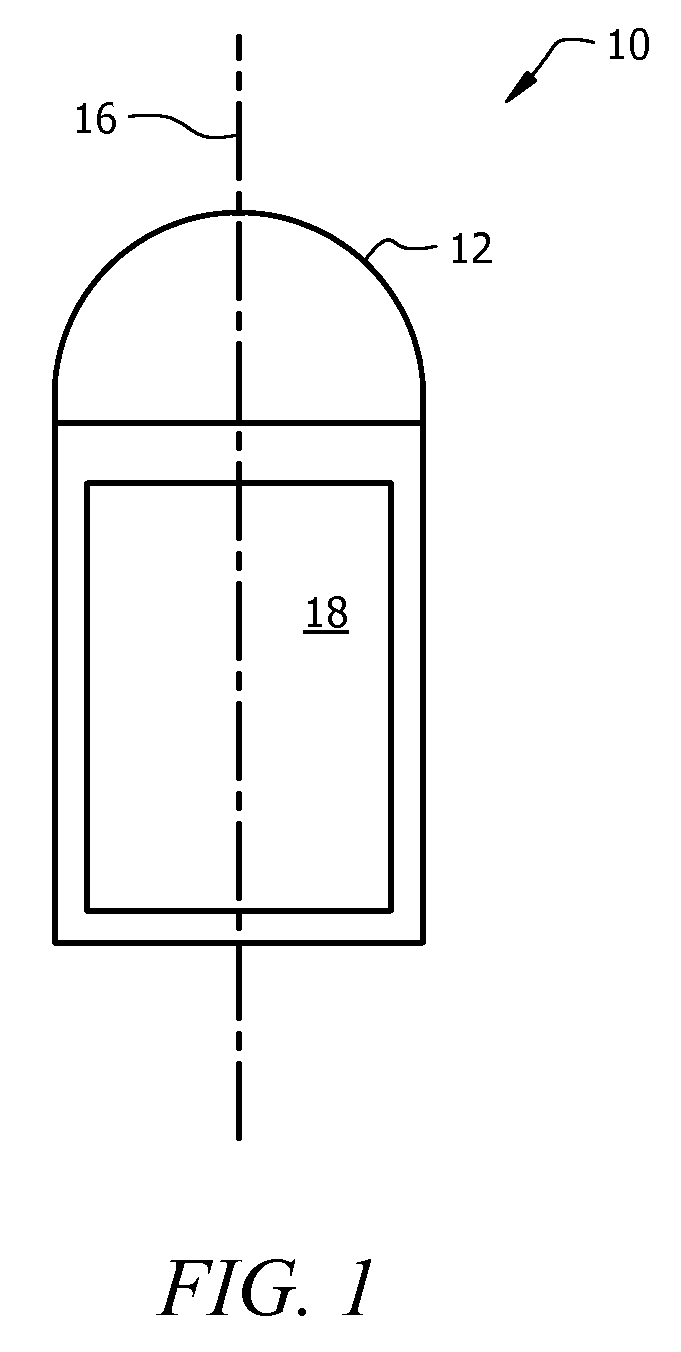
[0049]Referring now to FIG. 1, it will there be seen that a diagrammatic representation of a projectile or round equipped with the novel structure is denoted as a whole by the reference numeral 10.

[0050]Round 10 in this example is a typical 40 mm round. The novel command to arm fuze is denoted 12. Round 10, having been fired from a weapon, is depicted in flight, travelling in the direction of directional arrow 14. It is also spinning about longitudinal axis of symmetry 16 of round 10 and fuze 12. The trailing end of round 10 is filled with main explosive charge 18. As used herein, the leading end of any part is the end nearest the top of the drawing and the trailing end of any part is the end nearest the bottom of the drawing.

[0051]As best understood in connection with FIG. 2, fuze 12 includes hollow housing 20 having a generally inverted “U” shape, sometimes referred to in technical writings as a nosecone or an ogive. Hollow housing 20 houses all of the components of novel fuze 12....


PUM


Abstract

A mechanical safe and arm device for rotating munitions reduces arming scatter so that the “no arm” and “all arm” distance are substantially the same. A first spring holds a flywheel, a pinion gear, and a drive gear against rotation until centrifugal forces cause the spring to release them. The drive gear then rotates, causing rotation of the pinion gear and the flywheel. A post depending from the flywheel strikes and unlocks a second spring that unlocks a pivotally-mounted rotor that carries a detonator. The rotor then pivots and brings the detonator into alignment with a firing pin.

Description

BACKGROUND OF THE INVENTION[0001]1. Field of the Invention[0002]This invention relates, generally, to munitions. More particularly, it relates to a command to arm fuze that requires no electrical or electronic components.[0003]2. Description of the Prior Art[0004]Modern exploding munitions or rounds are required to carry insensitive explosives that have been specially formulated to prevent explosion resulting from exposure of the munitions or rounds to fire or mechanical abuse during transportation, storage, carrying in the field or any other environment they may encounter up until the moment they are fired from a weapon. Since a round must be “sensitive” if it is to explode upon impact with a target, a safe and arm device (SAD) is required to make the round “sensitive” once it has been fired from the weapon. The SAD does this by controlling the alignment of one or two additional explosive components with the main insensitive explosive which forms an explosive “train,” usually locat...

Claims


Application Information

Patent Timeline
IPC IPC(8): F42C15/26
CPCF42C15/188
Inventor TAYLOR, NORMAN C.
Owner AMTEC CORP
Learn More