Resonator optical gyroscope having input beam modulation optimized for high sensitivity and low bias

a gyroscope and input beam technology, applied in the direction of speed measurement using gyroscopic effects, instruments, surveying and navigation, etc., can solve the problems of high performance modulators, generating bias errors of gyro, and erroneous demodulation of rate signals, so as to maximize gyro s/n sensitivity, low intensity modulation, and high gyro s/n sensitivity

Active Publication Date: 2011-02-17
HONEYWELL INT INC
View PDF5 Cites 22 Cited by
  • Summary
  • Abstract
  • Description
  • Claims
  • Application Information

AI Technical Summary

Benefits of technology

[0006]More specifically, when the phase modulation amplitude is at certain values, the polarization cross-coupling induced intensity modulation can be nulled. By first setting the phase modulation amplitudes substantially close to these null points, e.g. M=3.832 or 7.016 radians (which causes the first order Bessel function to be zero J1(M)=0), then optimizing the modulation frequency, the intensity modulation can be reduced to nearly zero while still achieving maximum gyro S / N sensitivity. Selection of different (but substantially close to optimal sensitivity) modulation frequencies for CW and CCW input lightwaves avoids bias instabilities due to back-scattering in the gyro sensing loop.

Problems solved by technology

At a cross-coupling point after the phase modulator, the interferences between the light waves propagating along the two orthogonal polarization axes of the modulator causes intensity modulation at the phase modulation frequency, leading to erroneous demodulation of the rate signals.
Erroneous demodulation generates bias errors of the gyro.
These require high performance modulators and increase production complexity and cost.

Method used


Image

  • Resonator optical gyroscope having input beam modulation optimized for high sensitivity and low bias
  • Resonator optical gyroscope having input beam modulation optimized for high sensitivity and low bias
  • Resonator optical gyroscope having input beam modulation optimized for high sensitivity and low bias

Examples


Embodiment Construction

[0017]Reducing gyro bias errors and increasing gyro sensitivity is important to applications in many fields. The present invention provides methods and systems that optimize the input light modulations to simultaneously reduce bias errors and maximize sensitivity. It should be understood that resonator gyros can be constructed from many kinds of optical components (including those with optical fibers, optical waveguides, discrete optical components and free space, etc). In addition, the invention is applicable to gyros with multiple input light beams from one or multiple light sources in both CW and CCW directions.

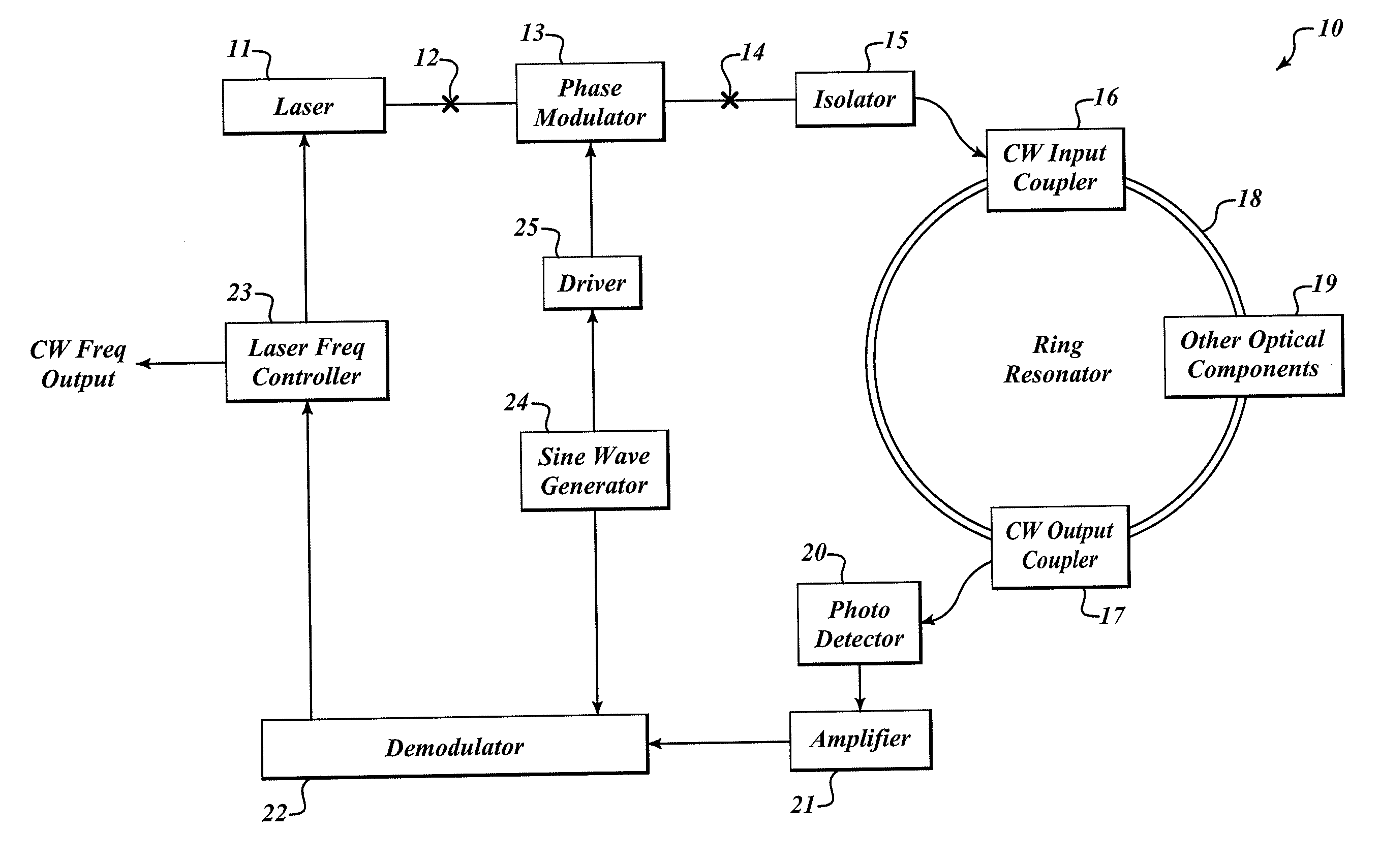
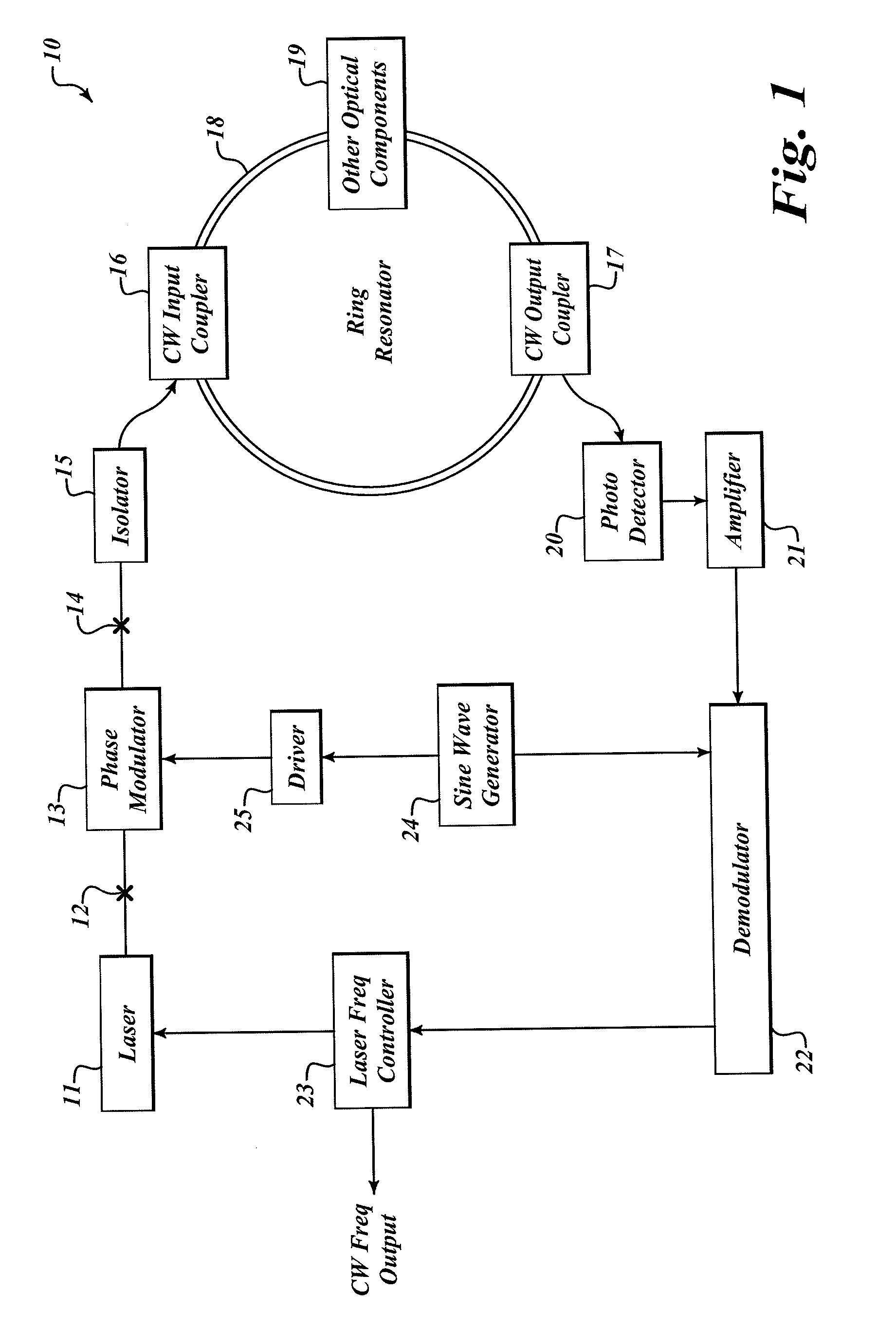
[0018]FIG. 1 shows a high sensitivity, low bias resonator optical gyroscope 10 (typically a resonator fiber optic gyroscope (RFOG)) with functional blocks for input light modulation, output signal detection, demodulation and servo electronics. The RFOG 10 includes a monochromatic light source 11, an input polarization cross-coupling point 12, a phase modulator 13, an outpu...


PUM


Abstract

Systems and methods for optimizing input beam modulation for high gyro sensitivity and low bias errors. The present invention is a resonator optical gyroscope having an optimized phase-modulation amplitude (frequency) for a selected modulation frequency (amplitude) that maximizes the gyro signal-to-noise (S / N) sensitivity. For selected values of the phase modulation amplitude, the polarization cross-coupling induced intensity modulation can be nulled. By setting the phase modulation amplitudes substantially close to these nulling points (e.g. M=3.832 or 7.016 radians, which causes the first order Bessel function to be zero J1(M)=0) and then optimizing the modulation frequency, the intensity modulation induced bias is reduced to zero and gyro S / N sensitivity is maximized.

Description

BACKGROUND OF THE INVENTION[0001]A resonator optical gyroscope is a rotation rate sensing device that includes a resonant cavity. The resonant cavity supports light waves propagating in opposite directions (without loss of generality, they are referred in the following to clockwise (CW) and counter-clockwise (CCW) directions, respectively). When there is a non-zero rotation rate around the normal axis of the resonator, the effective optical round-trip path length for the CW and CCW lightwaves is different, leading to a resonant frequency difference between them. By measuring this resonant frequency difference, rotation rate can be determined.[0002]Resonator fiber optic gyroscope (RFOG) is a special kind of resonator gyroscope that uses optical fibers in the resonator. Optical fiber increases the gyro signal-to-noise (S / N) sensitivity without significantly increasing the size of the sensing loop. For measuring the resonant frequency difference, monochromatic light waves are typically...

Claims


Application Information

Patent Timeline
Patent Type & Authority Applications(United States)
IPC IPC(8): G01C19/72
CPCG01C19/72
Inventor QIU, TIEQUNSANDERS, GLEN A.STRANDJORD, LEE
Owner HONEYWELL INT INC
Why Eureka
Try Eureka