
Temperature detecting device and method

a technology of temperature detection and temperature detection method, which is applied in the direction of instruments, heat measurement, calorimeters, etc., can solve the problem of increasing the fabricating cost of chips

Active Publication Date: 2011-02-17
SUNPLUS TECH CO LTD
View PDF11 Cites 14 Cited by
  • Summary
  • Abstract
  • Description
  • Claims
  • Application Information

AI Technical Summary

Benefits of technology

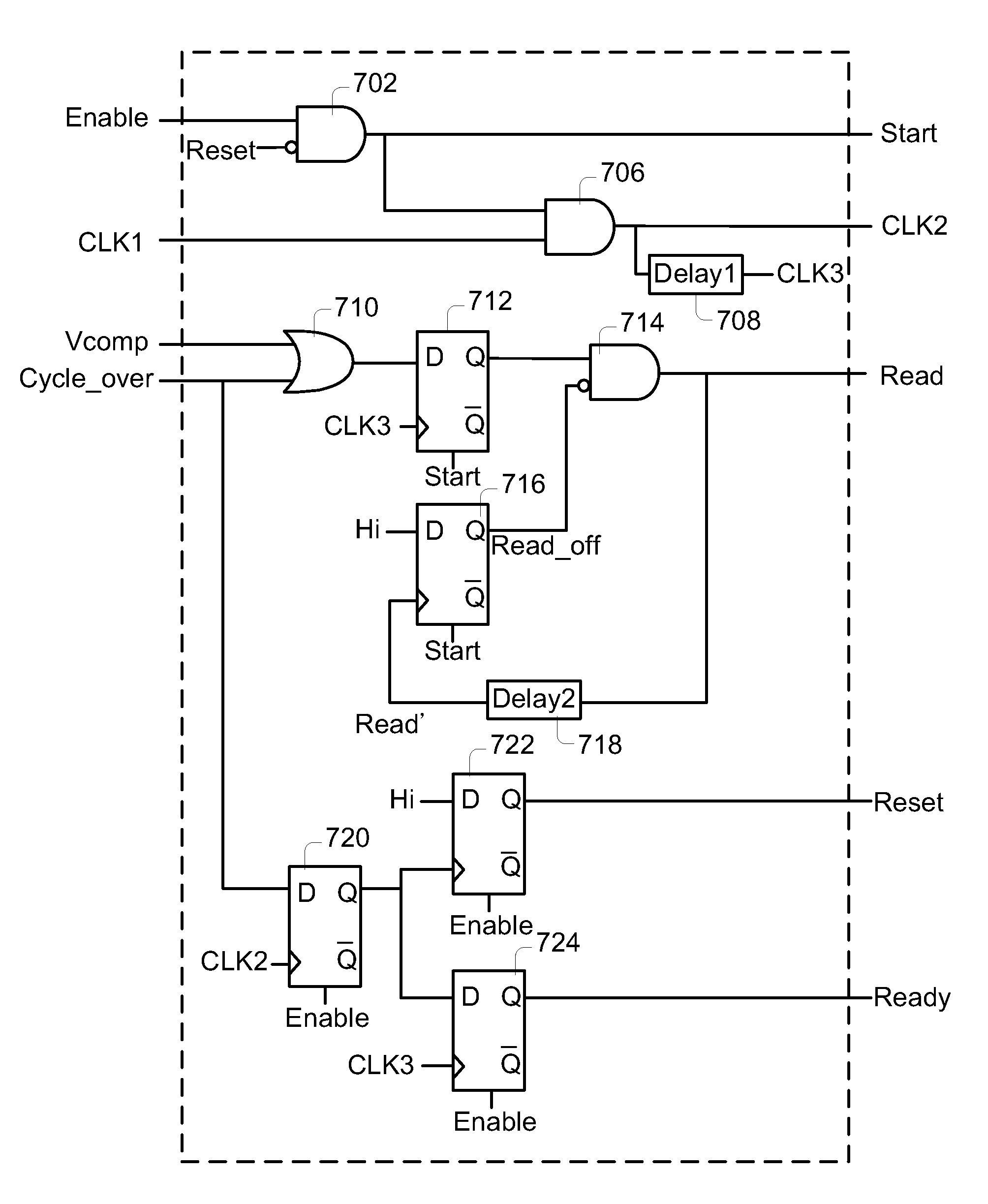
[0022]In accordance with an aspect of the present invention, there is provided a temperature detecting device. The temperature detecting device includes a current source, a plurality of resistors, a binary counter, a multiplexer, a comparator and a control logic. The current source provides a proportional to absolute temperature (PTAT) current. The resistors connected between the current source and a ground terminal in series for providing m voltage signals with ascending or descending voltages. The binary counter is used for counting in response to a start signal, thereby generating a binary select signal. The binary select signal is a (n+1)-bit select signal. The multiplexer has m input terminals for respectively receiving the m voltage signals. One of the m voltage signals is selectively outputted from the multiplexer as a multiplexer output signal according to the binary select signal, wherein 2n<m<2n+1. The comparator is used for comparing the multiplexer output signal with a reference voltage, thereby generating a comparing signal. The control logic is for issuing the start signal. If the comparing signal has a level change, the control logic controls the binary counter to record the binary select signal as a binary temperature signal. The reference voltage does not vary with temperature.

Problems solved by technology

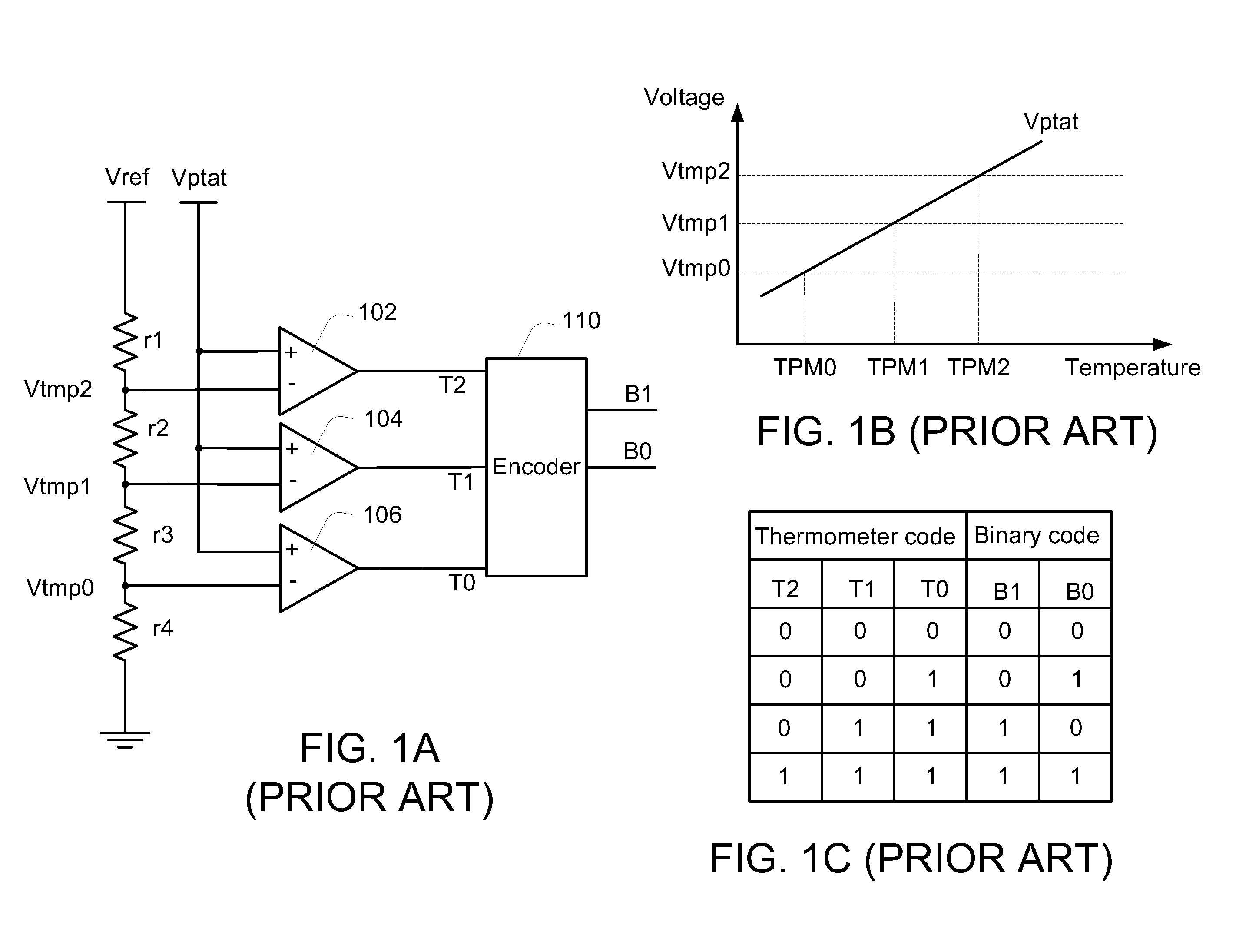
However, the temperature detecting device of FIG. 1A has too many comparators, which occupy much layout area of the chip and increase the fabricating cost of the chip.

Method used


Image

  • Temperature detecting device and method
  • Temperature detecting device and method
  • Temperature detecting device and method

Examples


Embodiment Construction

[0044]The present invention will now be described more specifically with reference to the following embodiments. It is to be noted that the following descriptions of preferred embodiments of this invention are presented herein for purpose of illustration and description only. It is not intended to be exhaustive or to be limited to the precise form disclosed.

[0045]FIG. 4 is a schematic circuit diagram illustrating a temperature detecting device according to an embodiment of the present invention. As shown in FIG. 4, the temperature detecting device comprises a plurality of resistors. These resistors are interconnected between a current source and a ground terminal in series. The current source outputs a PTAT (proportional to absolute temperature) current Iptat. The m nodes between these resistors respectively provide m voltage signals V0, V1, . . . , V(m−2) and V(m−1) to a multiplexer 420.

[0046]In each detecting cycle, a binary counter 410 counts from 0 to m, and produces a (n+1)-bit...


PUM

PropertyMeasurementUnit
absolute temperatureaaaaaaaaaa
voltagesaaaaaaaaaa
temperatureaaaaaaaaaa

Abstract

A temperature detecting device includes a current source, a plurality of resistors, a binary counter, a multiplexer, a comparator and a control logic. The current source provides a PTAT current. The resistors provide m voltage signals with ascending or descending voltages. The binary counter generates a binary select signal having (n+1) bits. The m voltage signals are selectively outputted from the multiplexer as a multiplexer output signal according to the binary select signal, wherein 2n<m<2n+1. The comparator is used for comparing the multiplexer output signal with a reference voltage, thereby generating a comparing signal. The control logic is for issuing the start signal. If the comparing signal has a level change, the control logic controls the binary counter to record the binary select signal as a binary temperature signal. The reference voltage does not vary with temperature.

Description

FIELD OF THE INVENTION[0001]The present invention relates to a temperature detecting device and a temperature detecting method, and more particularly to a temperature detecting device and a temperature detecting method for directly outputting a binary code.BACKGROUND OF THE INVENTION[0002]FIG. 1A is a schematic circuit diagram illustrating a temperature detecting device according to the prior art. As shown in FIG. 1A, four resistors r1, r2, r3 and r4 are serially connected between a reference voltage (Vref) and a ground terminal. The reference voltage (Vref) does not vary with temperature. The three nodes between these four resistors are respectively connected to negative input terminals of three comparators 102, 104 and 106 for providing three voltages Vtmp2, Vtmp1 and Vtmp0. The positive input terminals of the comparators 102, 104 and 106 are connected to a PTAT (proportional to absolute temperature) voltage Vptat. The PTAT voltage Vptat increases as the temperature rises. An enco...

Claims


Application Information

Patent Timeline
Patent Type & Authority Applications(United States)
IPC IPC(8): G01K7/16
CPCG01K2219/00G01K7/01
Inventor YI, BIN-WEICHENG, HUI-YI
Owner SUNPLUS TECH CO LTD
Learn More