
X-ray radiator

Inactive Publication Date: 2011-02-17
SIEMENS AG
View PDF11 Cites 7 Cited by
  • Summary
  • Abstract
  • Description
  • Claims
  • Application Information

AI Technical Summary

Benefits of technology

[0009]An object of the present invention to provide an x-ray radiator that can be thermally highly loaded, even given a compact structural shape.
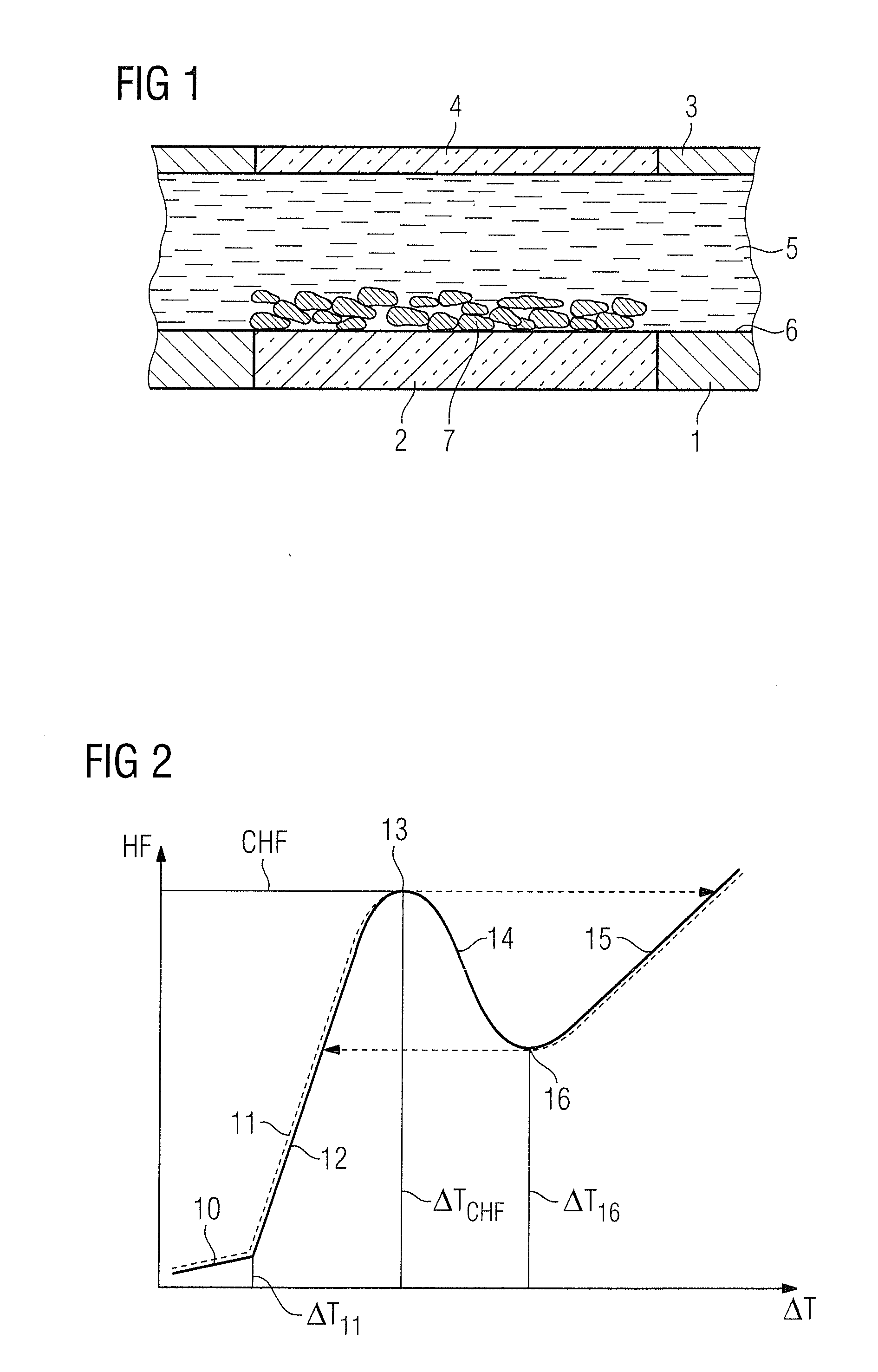
[0010]The x-ray radiator according to the invention has an x-ray tube that has a vacuum housing arranged in a radiator housing in which a coolant circulates. According to the invention, the vacuum housing has a porous coating, at least in parts thereof, on its surfaces facing the coolant. The boundary surface between the coolant and the surfaces facing the coolant (outer surface of the vacuum housing) that is used for the heat transfer is thereby increased without bubbles (which form given a partial vaporization of the coolant) rapidly hindering or completely interrupting the flow of heat. The heat transfer between the outer surfaces of the vacuum housing and the circulating coolant is thus improved, in particular given nucleate boiling.
[0011]The heat transfer coefficient, and therefore the heat transfer from the heated vacuum housing to the circulating coolant, are improved via the at least partial porous coating (according to the invention) of the vacuum housing at its surfaces that are facing towards the coolant.
[0012]Within the scope of preferred embodiments of the x-ray radiator according to the invention, the vacuum housing can be provided completely or only partially with the porous coating on its surfaces facing the coolant. Preferred regions of the vacuum housing for a partial porous coating are, for example, the x-ray exit window; the internal slide bearing cooling tube, the electron trap cooling surface and the back side of the anode. In the aforementioned regions, an increased temperature of the vacuum housing occurs (in particular given an x-ray radiator of compact design) that can be dissipated markedly better by the coolant circulating in the radiator housing via an at least partial porous coating.

Problems solved by technology

The shrinking of the structural size in these components is limited by the previously achievable heat transfer coefficients at the cooling surfaces.

Method used


Image

  • X-ray radiator
  • X-ray radiator

Examples


Embodiment Construction

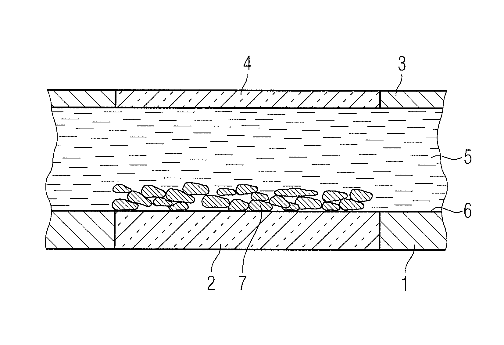
[0018]A vacuum housing of an x-ray tube is designated with 1 in FIG. 1. T x-ray tube has an x-ray exit window 2. The vacuum housing of the x-ray tube is arranged in a radiator housing 3 that has a beam exit window 4 aligned with the x-ray exit window 2. A coolant 5 (water, oil) circulates in the radiator housing 3. The coolant 5 discharges the heat created in the generation of the usable x-ray radiation. According to the invention, the vacuum housing 1 is at least partially covered by porous coating 7 on its surfaces 6 facing the coolant 5.

[0019]It is not important whether the surfaces 6 facing the coolant 5 (outer surfaces of the vacuum housing 1) are geometrically structured in order to provide a larger surface area for heat transfer, such as by having ridges, cooling fins or the like that are also provided with the porous coating 7.

[0020]In the shown exemplary embodiment, the porous coating 7 is applied to the x-ray exit window 2. The porous coating 7 on the x-ray exit window 2 c...


PUM


Abstract

An x-ray radiator has an x-ray tube with a vacuum housing arranged in a radiator housing in which a coolant circulates. The vacuum housing has a porous coating, at least at parts thereof, on surfaces facing the coolant. The heat transfer between the vacuum housing and the coolant is thereby improved, such that the x-ray radiator can be more highly thermally loaded.

Description

BACKGROUND OF THE INVENTION[0001]1. Field of the Invention[0002]The invention concerns an x-ray radiator of the type having an x-ray tube that has a vacuum housing arranged in a radiator housing in which a coolant circulates.[0003]2. Description of the Prior Art[0004]An x-ray radiator of the above type has a radiator housing in which the x-ray tube is arranged so as to be rigid (stationary or fixed anode x-ray tube, or rotating anode x-ray tube) or rotatable (rotating piston x-ray tube).[0005]In the x-ray tube, electrons are thermally generated by an x-ray source (filament, surface emitter) and accelerated toward an anode (stationary anode or rotating anode). Upon impact of the electrons on the anode, usable x-ray radiation is generated that exits the vacuum housing through an x-ray exit window. In the generation of the usable x-ray radiation, more than 99% of the energy that is used is converted into heat. This heat must be effectively dissipated by a cooling system during the oper...

Claims


Application Information

Patent Timeline
IPC IPC(8): H01J35/12
CPCH01J35/16H01J35/18H01J2235/168H01J2235/1283H01J2235/122
Inventor FREUDENBERGER, JOERG
Owner SIEMENS AG
Learn More