Decentralized electric brake system

a brake system and decentralized technology, applied in the field of vehicle brake systems, can solve the problems of limited anti-skid capabilities, inability to dispatch aircraft, and inability to achieve normal braking mode, so as to reduce the weight of the vehicle, reduce the speed of the transducer and other cable runs, and ensure the effect of reliable operation

Active Publication Date: 2011-02-17
MEGGITT AIRCRAFT BRAKING SYST
View PDF16 Cites 26 Cited by
  • Summary
  • Abstract
  • Description
  • Claims
  • Application Information

AI Technical Summary

Benefits of technology

[0006]Still a further aspect of the invention is the provision of a decentralized electric brake system which includes antiskid control associated with each of the electromechanical actuator controllers of the brake system, in combination with dual output wheel speed transducers, allowing the braking system to retain antiskid functionality on all wheels in the event of a single failure of an actuator.
[0007]Yet another aspect of the invention is the provision of a decentr...

Problems solved by technology

However, these systems can have limited antiskid capabilities.
In this configuration, the antiskid capabilities are generally limited to normal braking mode only, and not applicable to an alternate or emergency braking mode associated with the br...

Method used


Image

  • Decentralized electric brake system
  • Decentralized electric brake system
  • Decentralized electric brake system

Examples


Embodiment Construction

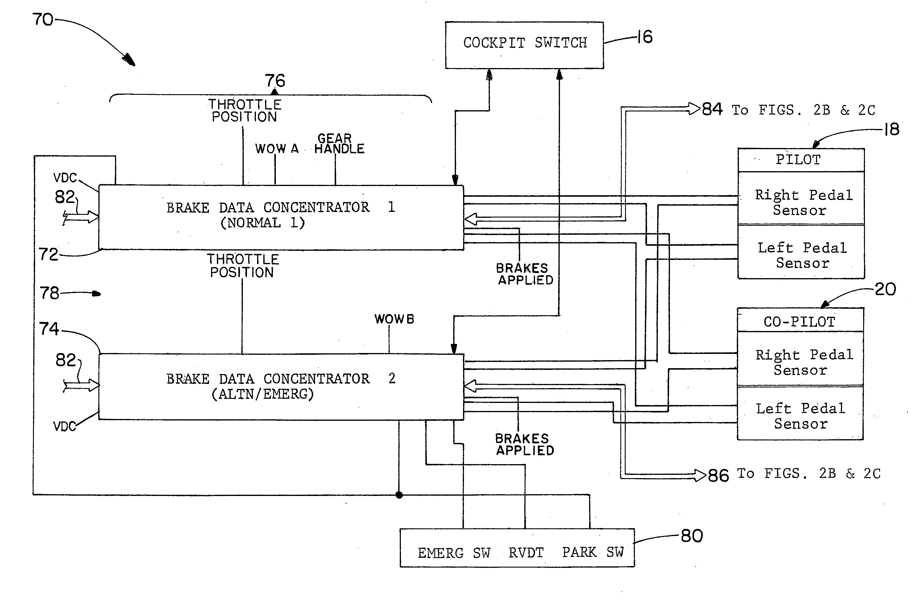
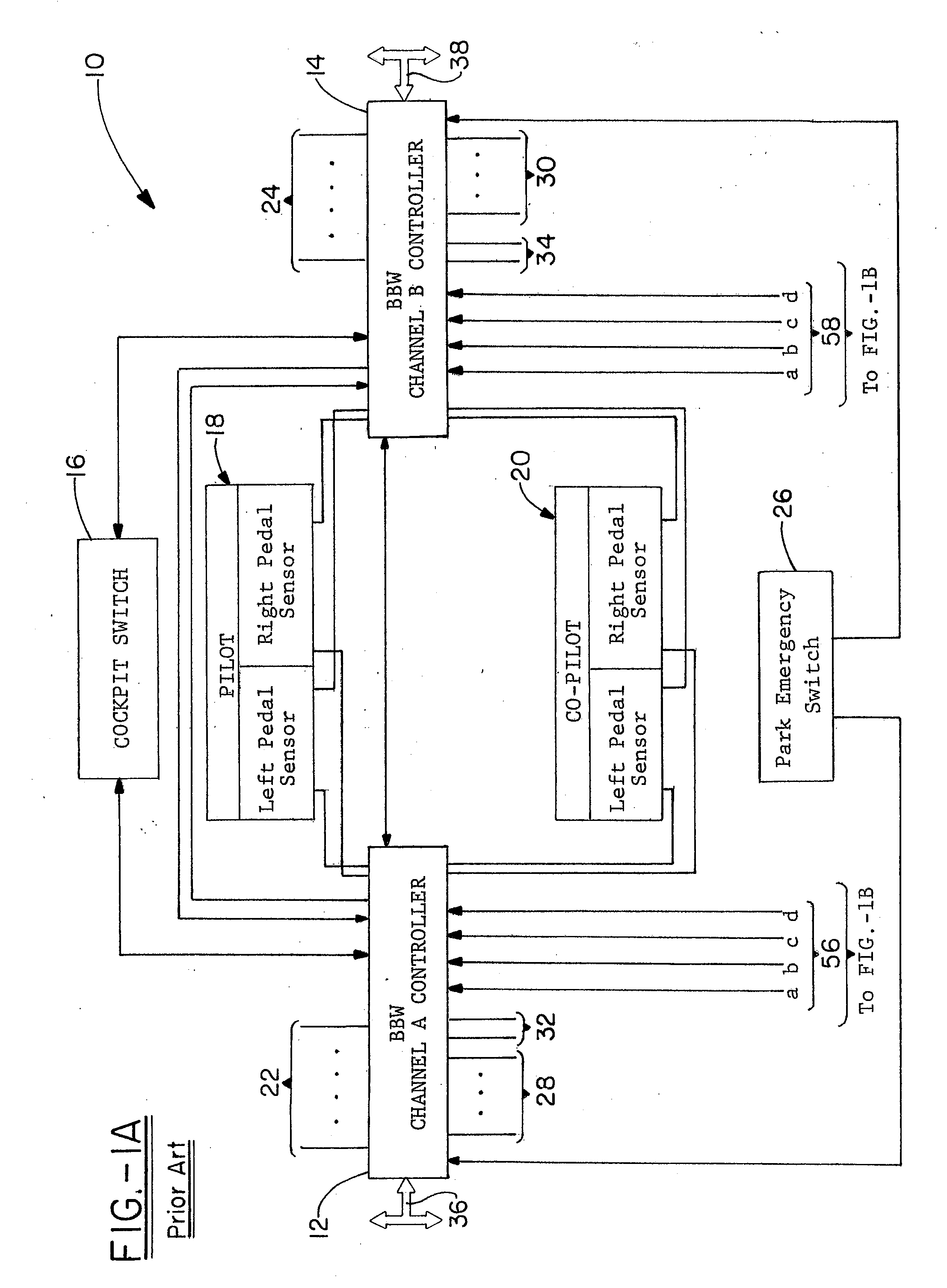
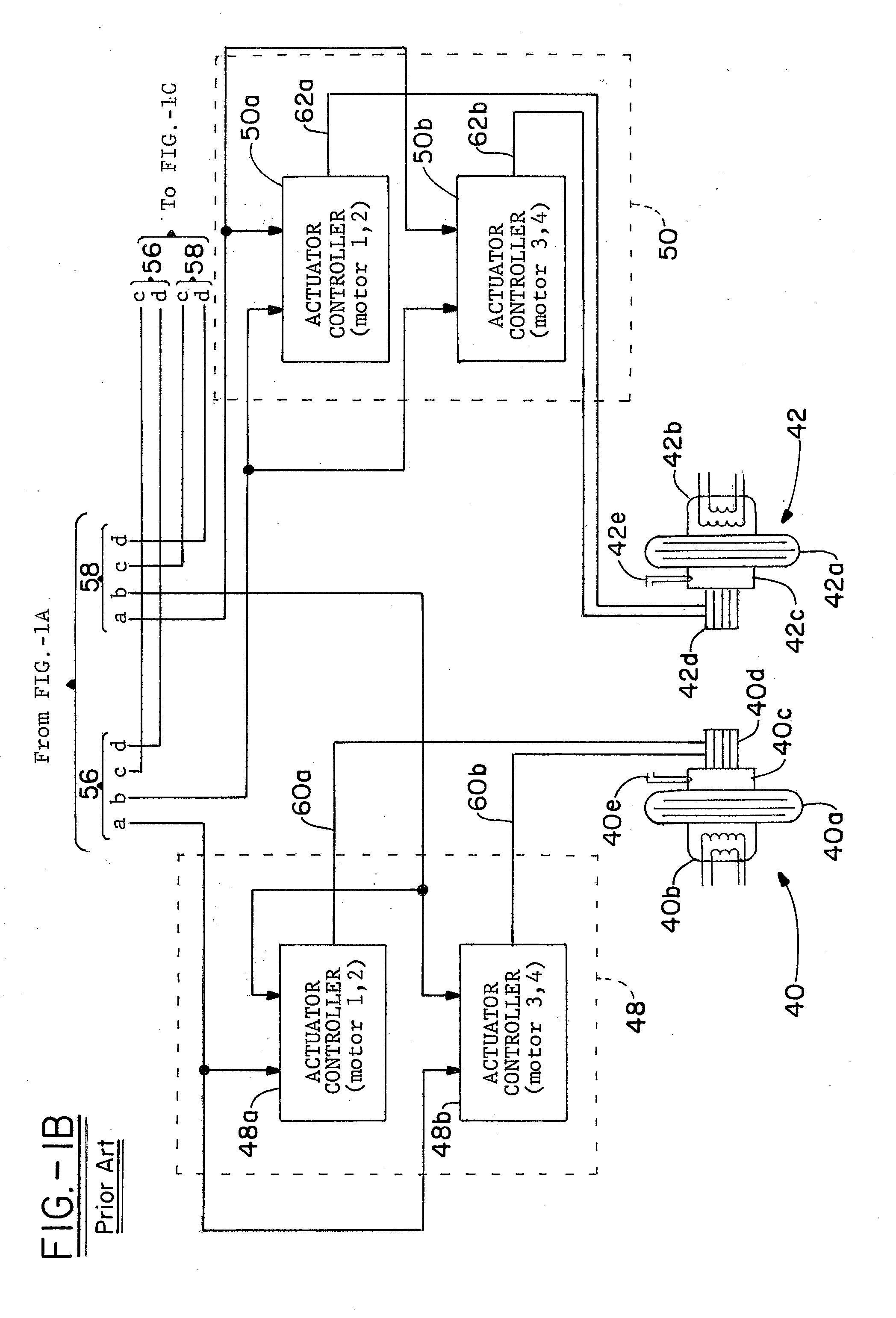
[0015]Referring now to the drawings and more particularly FIG. 1, it can be seen that a brake control system made in accordance with the prior art is designated generally by the numeral 10. The system 10 is presented and described herein with regard to a particularly illustrated brake system architecture, although those skilled in the art will readily appreciate its adaptability to a broad range of architectures. The brake control system 10 is shown illustratively as a brake-by-wire system, in which the braking activity and control signals relevant thereto are all electrical, rather than hydraulic. The brake control system 10 includes a pair of controllers 12, 14 to provide for a degree of failsafe redundancy. As will be appreciated by those skilled in the art, and be apparent later herein, the controllers 12, 14 process and provide for generation of all of the requisite brake control signals for operating the system 10. The controllers 12, 14 provide for the generation of brake app...


PUM


Abstract

An electric aircraft brake control system has a plurality of wheel and brake assemblies, each having a wheel, wheel speed transducer, brake assembly and a brake actuator. Electromechanical control units are uniquely associated with and connected to certain of the wheel and brake assemblies, and each of the electromechanical control units is provided with an antiskid system as an integral portion thereof. Brake data concentrators are provided for receiving data corresponding to various aircraft operational parameters, including brake pedal position, and provide operational signals to the electromechanical control unit as a function thereof. A controller for emergency and park braking is connected to the electromechanical actuator controllers through one of the brake data concentrators to effect emergency braking action on the brake assemblies, such emergency braking action having incident antiskid control. The system allows for a redundency in brake control circuitry and operation, which increases the dispatchability of an associated aircraft by ensuring continued effective operation of the aircraft even in view of a failure of one of the redundant circuits or systems. A reduction in weight is also achieve by reducing lengthy cable runs.

Description

TECHNICAL FIELD[0001]The invention herein resides in the art of vehicle braking systems and, more particularly, to an aircraft braking system. Specifically, the invention relates to electric brake systems for use on aircraft, in which the antiskid portion of the braking system is located in and associated with discrete electromechanical actuator controllers uniquely associated with the brakes of the aircraft. The invention specifically relates to the utilization of electromechanical actuator controllers that ensure antiskid functionality in both normal and alternate or emergency braking operation modes.BACKGROUND OF THE INVENTION[0002]The use of electric brakes in aircraft systems is becoming increasingly popular. In such systems, electric motors are employed to drive a piston through gears, screws and the like, into a pressure plate of a brake disc stack. Typically, a plurality of actuators are associated with each brake assembly, generally being uniformly distributed thereabout. P...

Claims


Application Information

Patent Timeline
IPC IPC(8): G06F17/00
CPCB60T8/1703B60T8/325B60T2270/413B60T2270/402B60T8/885
Inventor HILL, JAMES L.BURKHALTER, KURT
Owner MEGGITT AIRCRAFT BRAKING SYST
Why Eureka
Try Eureka