Method and Device for Generating Compressed Air and for Blowing it into an Internal Combustion Engine

a technology of compressed air and internal combustion engine, which is applied in the direction of engine components, exhaust gas recirculation, non-fuel substance addition to fuel, etc., can solve the problems of no compressed fresh gas available, and the problem of blowing air in the case of vehicles without compressed air with them, so as to improve the circulation of exhaust gas

Active Publication Date: 2011-02-24
KNORR-BREMSE SYST FUER NUTZFAHRZEUGE GMBH
View PDF29 Cites 42 Cited by
  • Summary
  • Abstract
  • Description
  • Claims
  • Application Information

AI Technical Summary

Benefits of technology

[0004]In engines with exhaust gas circulation, it is in addition desirable that sufficient fresh air is still fed to the engine in addition to the exhaust gas in order to avoid putting the dynamics of the engine at risk. Here too, the exhaust gas turbocharger is capable of feeding sufficient fresh air only if it is operated by a sufficient flow of exhaust gas. The active blowing in of air is also capable of contributing significantly to improving the engine dynamics here.
[0008]The object of the present invention is therefore to make available a method and a device for generating compressed air and blowing it into an internal combustion engine in which the above disadvantages are eliminated or significantly reduced and further advantages are obtained.
[0010]This advantageously ensures that an over-run fuel cutoff mode of a motor vehicle is utilized to thereby generate compressed air. This is particularly advantageous when a compressed air brake system with all its components is not present.
[0014]In a repeating operating mode, that is to say over-run fuel cutoff phases are followed by acceleration phases, and vice versa, the storage of the compressed air is necessary only for a brief time. Here, it is not required of the compressed air generating means that it must always make available sufficient compressed air, as is the case, for example, in a compressed air brake system. Specifically, the storage of the compressed air for the blowing in of air does not have to be made as complex for only a brief storage time as the storage of compressed air in a compressed air brake system. In particular, it is possible to dispense with the drying of air as long as the condensation water which is produced is discharged from the reservoir vessel, for example by a water separator. The internal combustion engine can advantageously basically be supplied with non-dried air.
[0015]In a further embodiment, the gas feed device is a fresh gas line section of a device for supplying fresh air for the controlled blowing in of compressed air. Here, a combination of the advantages of the blowing in of compressed air in terms of what is referred to as “turbo lag” as well as those of improved exhaust gas circulation are obtained.

Problems solved by technology

Here, when the throttle is opened the internal combustion engine does not react with an increase in the rotational speed until after a certain delay time during which exhaust gas energy is not available, i.e., is sufficient exhaust gas pressure is not available to drive the exhaust gas turbocharger, and therefore no compressed fresh gas is available.
The blowing in of air in the case of vehicles which do not carry any compressed air with them is problematic.

Method used


Image

  • Method and Device for Generating Compressed Air and for Blowing it into an Internal Combustion Engine
  • Method and Device for Generating Compressed Air and for Blowing it into an Internal Combustion Engine

Examples


Embodiment Construction

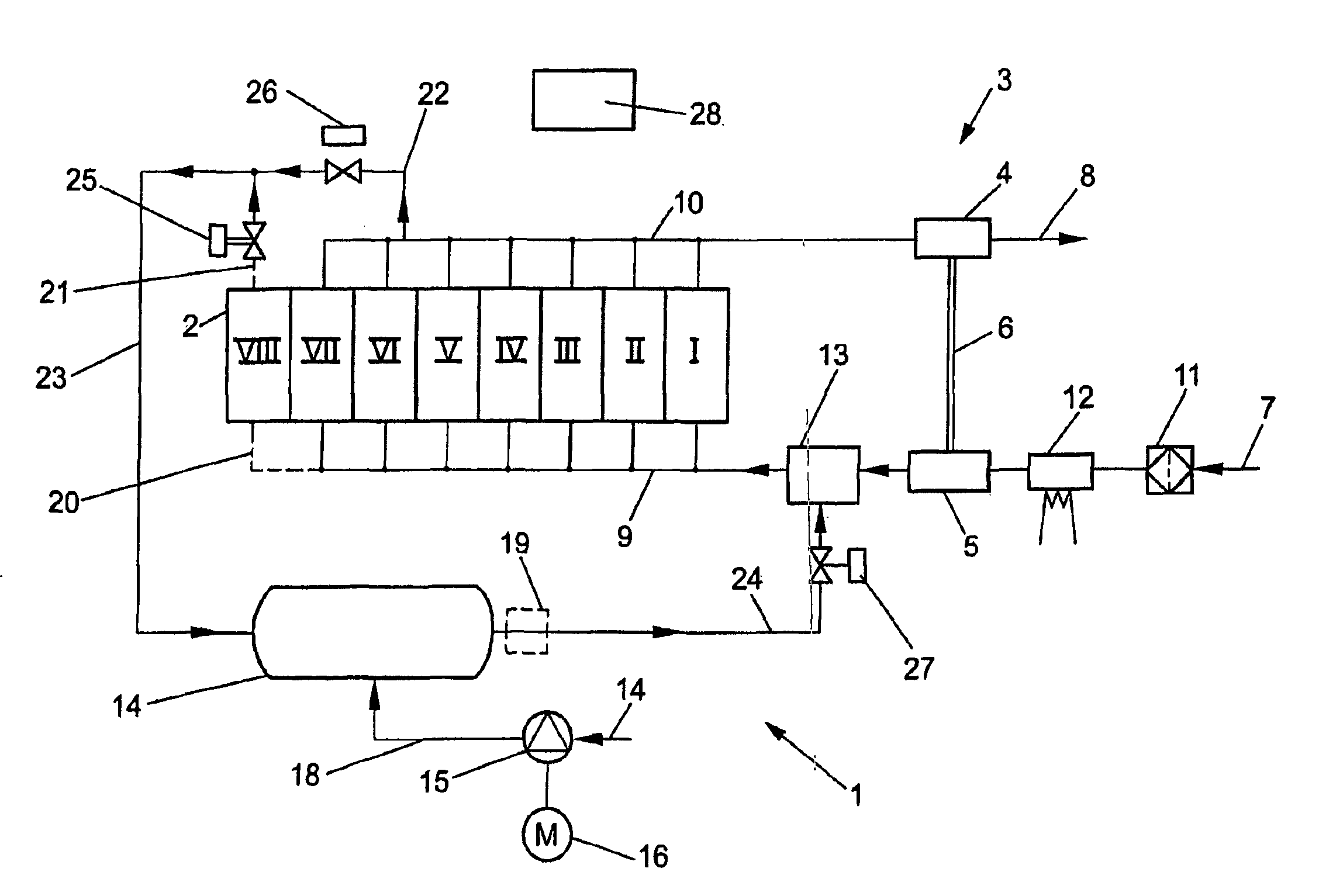
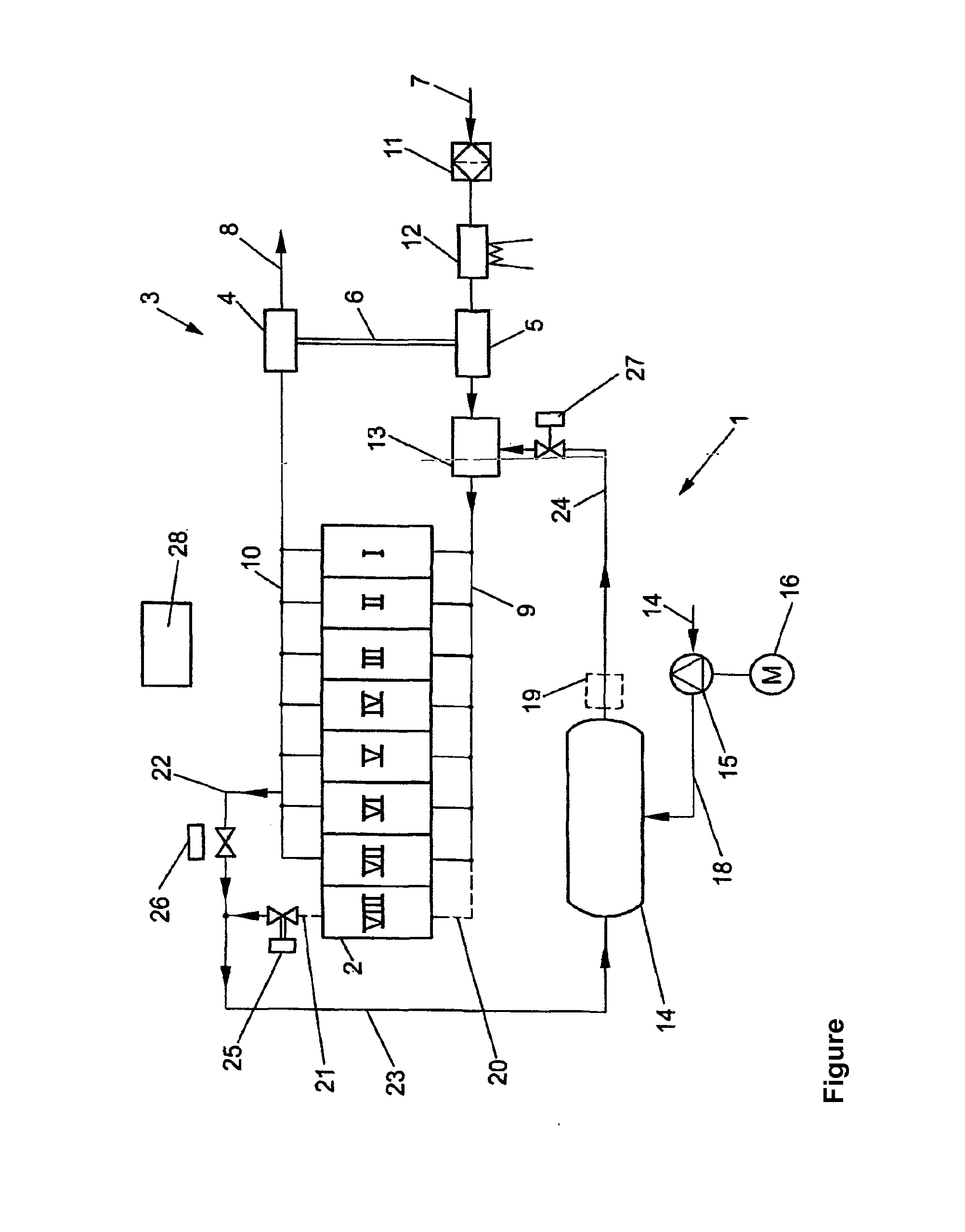
[0018]The FIGURE is a schematic illustration of an internal combustion engine 2 with an exhaust gas turbocharger 3 and an inventive device 1 for generating compressed air and blowing it in.

[0019]In the illustrated example, the internal combustion engine 2 is a diesel engine with eight cylinders I to VIII, an intake line 9 and an exhaust line 10. An air inlet 7 is connected via an air filter 11 to an intake air preheating means 12 which is connected to a compressor 5 of the exhaust gas turbocharger 3. This is adjoined by a gas feed device 13 which opens into the intake line 9. The compressor 5 of the exhaust gas turbocharger 3 is coupled to an exhaust gas turbine 4 of the exhaust gas turbocharger 3 via a coupling 6, for example a shaft. The exhaust gas turbine 4 is arranged in the exhaust line 10 upstream of an exhaust gas outlet 8 for the exhaust gas of the internal combustion engine 2, and is driven by an exhaust gas flow.

[0020]The gas feed device 13 has here a port with a blowing-...


PUM


Abstract

The invention relates to a method for producing compressed air and for injecting the same in an internal combustion engine, in particular a diesel motor, comprising an exhaust turbocharger. The method has the following steps: determination of operating parameters of the internal combustion engine to identify operating states of the internal combustion engine; production of compressed air by the internal combustion engine using the determined operating parameter in an operating state without combustion and storage of the produced compressed air; and injection of the stored compressed air into the combustion engine using the determined operating parameter in an operating state with combustion of the internal combustion engine in order to increase the pressure in an induction cycle. The invention also relates to a corresponding device.

Description

[0001]This application is a continuation of PCT International Application No. PCT / EP2009 / 000938, filed Feb. 11, 2009, which claims priority under 35 U.S.C. §119 to German Patent Application No. DE 10 2008 008 723.8, filed Feb. 12, 2008, the entire disclosures of which are herein expressly incorporated by reference.BACKGROUND AND SUMMARY OF THE INVENTION[0002]The invention relates to a method and a device for generating compressed air and blowing it into an internal combustion engine, in particular a diesel engine, having an exhaust gas turbocharger.[0003]Such internal combustion engines, for example piston engines such as diesel engines, with an exhaust gas turbocharger have, for example, an operating state during acceleration which is referred to as “turbo lag”. Here, when the throttle is opened the internal combustion engine does not react with an increase in the rotational speed until after a certain delay time during which exhaust gas energy is not available, i.e., is sufficient...

Claims


Application Information

Patent Timeline
Patent Type & Authority Applications(United States)
IPC IPC(8): F02D23/00F02B37/16
CPCF02B29/0406F02M25/0707F02D17/023F02D13/04F02B21/00F02M26/05
Inventor MAYR, MATHIAS
Owner KNORR-BREMSE SYST FUER NUTZFAHRZEUGE GMBH
Why Eureka
Try Eureka