Process for producing biopolymer nanoparticles

a biopolymer nanoparticle and nanoparticle technology, applied in the field of biopolymer nanoparticle production process, can solve the problems that the process described in u.s. patent no. 6,677,386 may not be able to keep up with the increasing demand for biopolymer nanoparticles, and achieve the effect of increasing the control of the viscosity of colloidal dispersion and increasing production rates

Active Publication Date: 2011-02-24
ECOSYNTHETIX INC
View PDF29 Cites 35 Cited by
  • Summary
  • Abstract
  • Description
  • Claims
  • Application Information

AI Technical Summary

Benefits of technology

[0017]A process according to the invention may achieve complete or near complete gelatinization of the biopolymer feedstock. Advantageously, the process achieves removal of virtually all of any native biopolymer (e.g. starch) crystalline structure before the crosslinking reaction such that the crystalline structure is not detectable using standard techniques (e.g. cross-polarization microscopy). A process according to the invention meets the challen

Problems solved by technology

However, there are concerns that the process described in U.S. Pat. No. 6,677,386 ma

Method used


Image

  • Process for producing biopolymer nanoparticles
  • Process for producing biopolymer nanoparticles
  • Process for producing biopolymer nanoparticles

Examples


examples

[0061]The following examples serve to illustrate the invention and are not intended to limit the invention in any way.

[0062]Specific feed and run conditions are listed in Table A and Table B.

examples 1 and 2

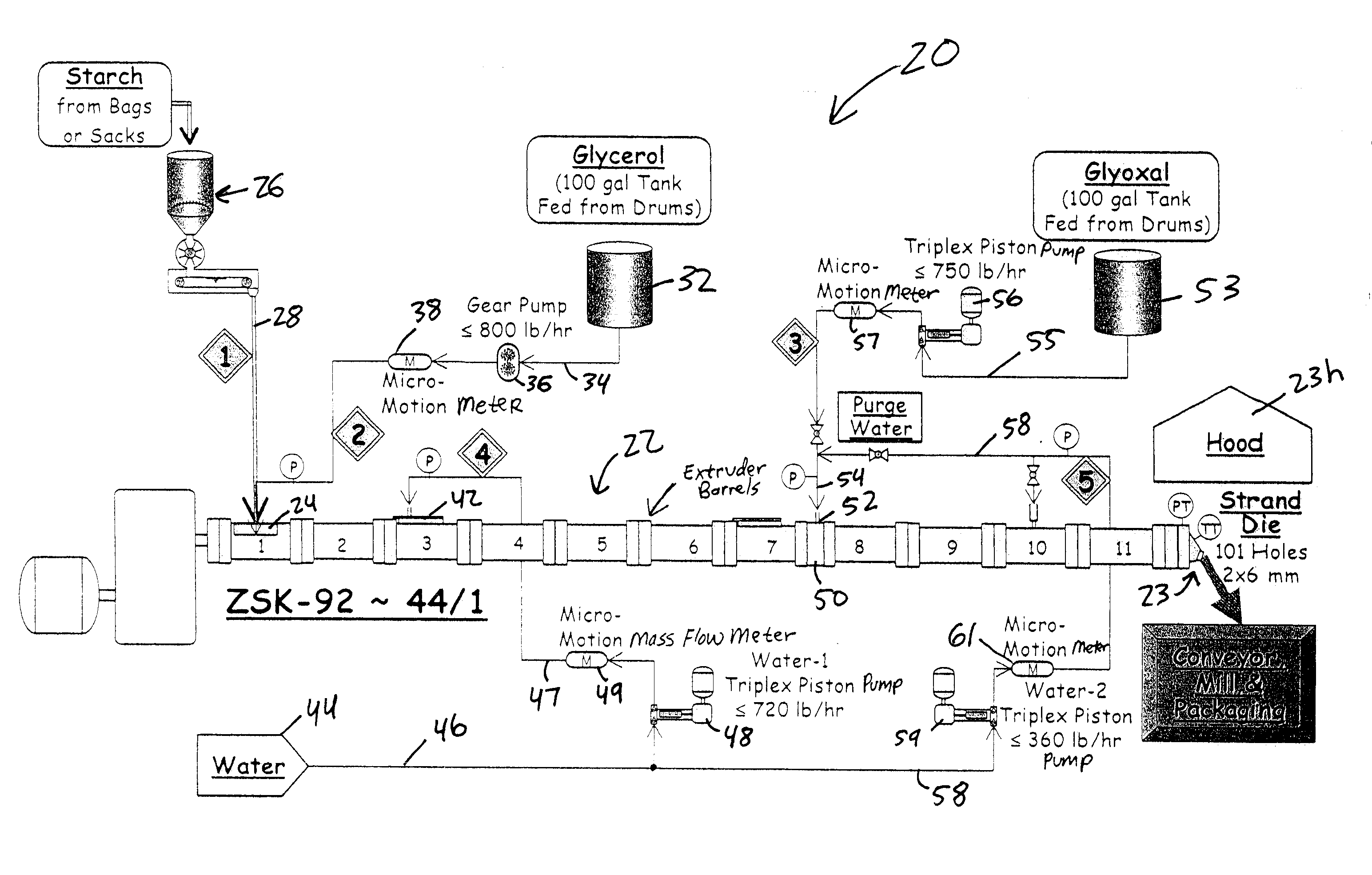
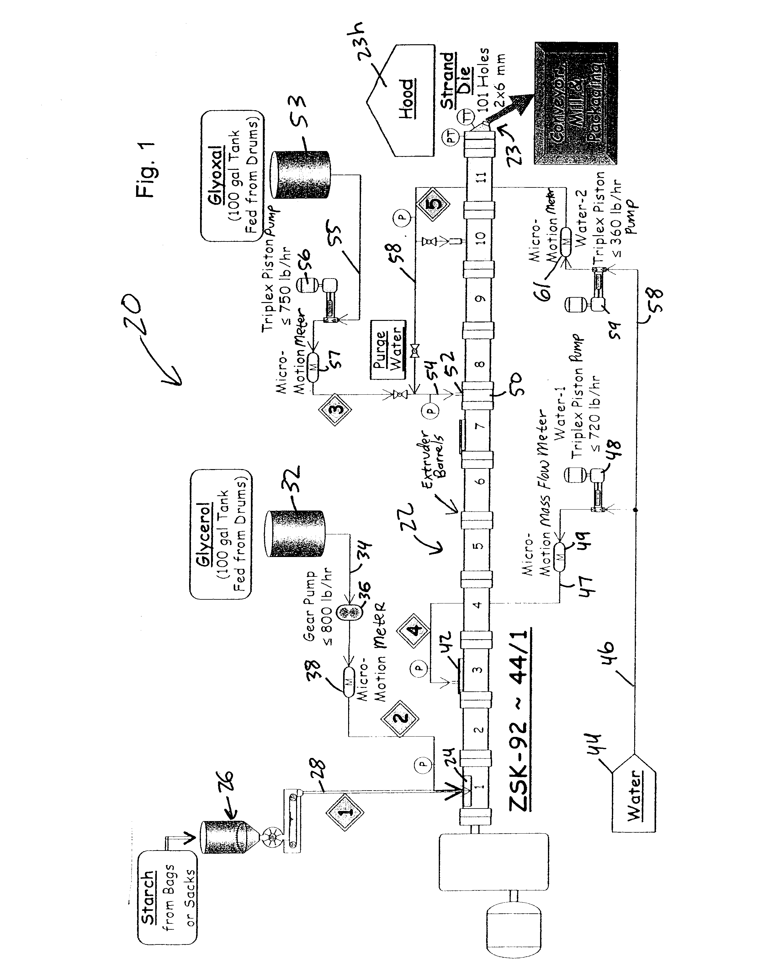
[0063]Examples 1 and 2 represent the initial scale up from a ZSK-58 extruder to a ZSK-92 twin screw extruder. See Screw #58-1 and 92-1 in FIG. 3. One extra barrel of solids conveying was used on the 92 mm extruder because an eight barrel configuration was not available. Because Screw #58-1 of FIG. 3 was deemed too strong (meaning this screw design put too much energy into the product), three left hand kneading blocks were removed from the gelatinization zone and one from the reaction zone for Screw #92-1 of FIG. 3. Also, an extra water injection was added along with the glyoxal (crosslinker) solution to allow evaluation of the effects of its concentration. As received, the glyoxal solution is 40% active in water. At two parts of glyoxal, this is equivalent to a base or minimum of 3 parts of water with it if no additional water is used. (See Table A.)

[0064]On startup, a preliminary gelatinization experiment without a die was run at 726 kg / hr and 300 rpm for a specific rate of 2.42 kg...

example 3

[0066]Example 3 is similar to Example 2 but represents a reduction in the quantity of water added downstream with the glyoxal (crosslinker) to determine the effect on the product viscosity. The extra water was reduced from 3.0 to 2.1 parts. The screw speed for Example 3 was 5% higher than that for Example 2. There was not a significant effect on the end product viscosity (measured as a standard 25% solids aqueous dispersion at 25° C. and 100 rpm on a Brookfield viscometer). More notably, viscosity was slightly higher even though the SME was about 10% higher in Example 3 due to the water and extruder rpm differences. In previous work, higher shear rates have resulted in lower dispersion viscosities. This is contrary to that and demonstrates that there are other controlling factors that affect viscosity. As with Example 2, steam back venting shut the line down after a short time.


PUM

PropertyMeasurementUnit
Temperatureaaaaaaaaaa
Fractionaaaaaaaaaa
Angleaaaaaaaaaa

Abstract

A process for producing a biopolymer nanoparticles product is disclosed. In this process, biopolymer feedstock and a plasticizer are fed to a feed zone of an extruder having a screw configuration in which the feedstock is process using shear forces in the extruder, and a crosslinking agent is added to the extruder downstream of the feed zone. The biopolymer feedstock and plasticizer are preferably added separately to the feed zone. The screw configuration may include two or more steam seal sections. Shear forces in a first section of the extruder may be greater than shear forces in an adjacent second section of the extruder downstream of the first section. In a post reaction section located after a point in which the crosslinking reaction has been completed, water may be added to improve die performance.

Description

CROSS-REFERENCES TO RELATED APPLICATIONS[0001]This application claims priority from U.S. Provisional Patent Application No. 60 / 837,669 filed Aug. 15, 2007.STATEMENT REGARDING FEDERALLY SPONSORED RESEARCH[0002]Not Applicable.BACKGROUND OF THE INVENTION[0003]1. Field of the Invention[0004]This invention relates to a process for producing biopolymer nanoparticles and in particular, starch nanoparticles.[0005]2. Description of the Related Art[0006]U.S. Pat. No. 6,677,386 (which corresponds to WO 00 / 69916) describes a process for producing biopolymer nanoparticles, which in one form are starch nanoparticles. In the process, the biopolymer is plasticized using shear forces, and a crosslinking agent is added during the processing. After the processing, the biopolymer nanoparticles can be dispersed in an aqueous medium. One version of the process results in starch nanoparticles which are characterized by an average particle size of less than 400 nanometers.[0007]U.S. Pat. No. 6,677,386 note...

Claims


Application Information

Patent Timeline
IPC IPC(8): B29C47/36B29C47/10B29C48/58B82Y40/00
CPCB29C47/0004B29C47/6062B29C47/1063B29C47/60B29C47/6037B29K2003/00B29K2105/0005C08B31/003C08J3/24C08J2303/02C08K5/0025C08L3/02B29B9/06B29B2009/125B29B9/00B29B9/08B29K2105/0038B29C47/1081B29C47/6031B29C47/6056B29C47/6087B29C47/0014B29B7/46B29B7/603B29B7/726B29B7/845B29B7/94B29C48/40B29C48/57B29C48/05B29C48/54B29C48/55B29C48/575B29C48/625B29C48/022B29C48/29B29C48/297B29B9/12B29C48/58B29C31/00C08B30/00
Inventor WILDI, ROBERT H.VAN EGDOB, EDWARDBLOEMBERGEN, STEVEN
Owner ECOSYNTHETIX INC
Why Eureka
Try Eureka