Light-emitting device

a technology of light-emitting devices and light-emitting tubes, which is applied in the direction of discharge tubes/lamp details, instruments, luminescent screens of discharge tubes, etc., can solve the problems of not finding a method that can satisfy both brightness and achieves excellent color gamut (ntsc ratio), efficient light absorption and white light high efficiency

Active Publication Date: 2011-02-24
GE PHOSPHORS TECH LLC
View PDF6 Cites 44 Cited by
  • Summary
  • Abstract
  • Description
  • Claims
  • Application Information

AI Technical Summary

Benefits of technology

[0020]According to the present invention, there is provided a light-emitting device capable of obtaining white light having significantly excellent color gamu

Problems solved by technology

In this field, various methods are proposed, however, a method satisfying both brightness and color gamut (NTSC ratio) has not been found yet.
However, Patent document 2 lacks concrete description concer

Method used


Image

  • Light-emitting device
  • Light-emitting device
  • Light-emitting device

Examples


example 1

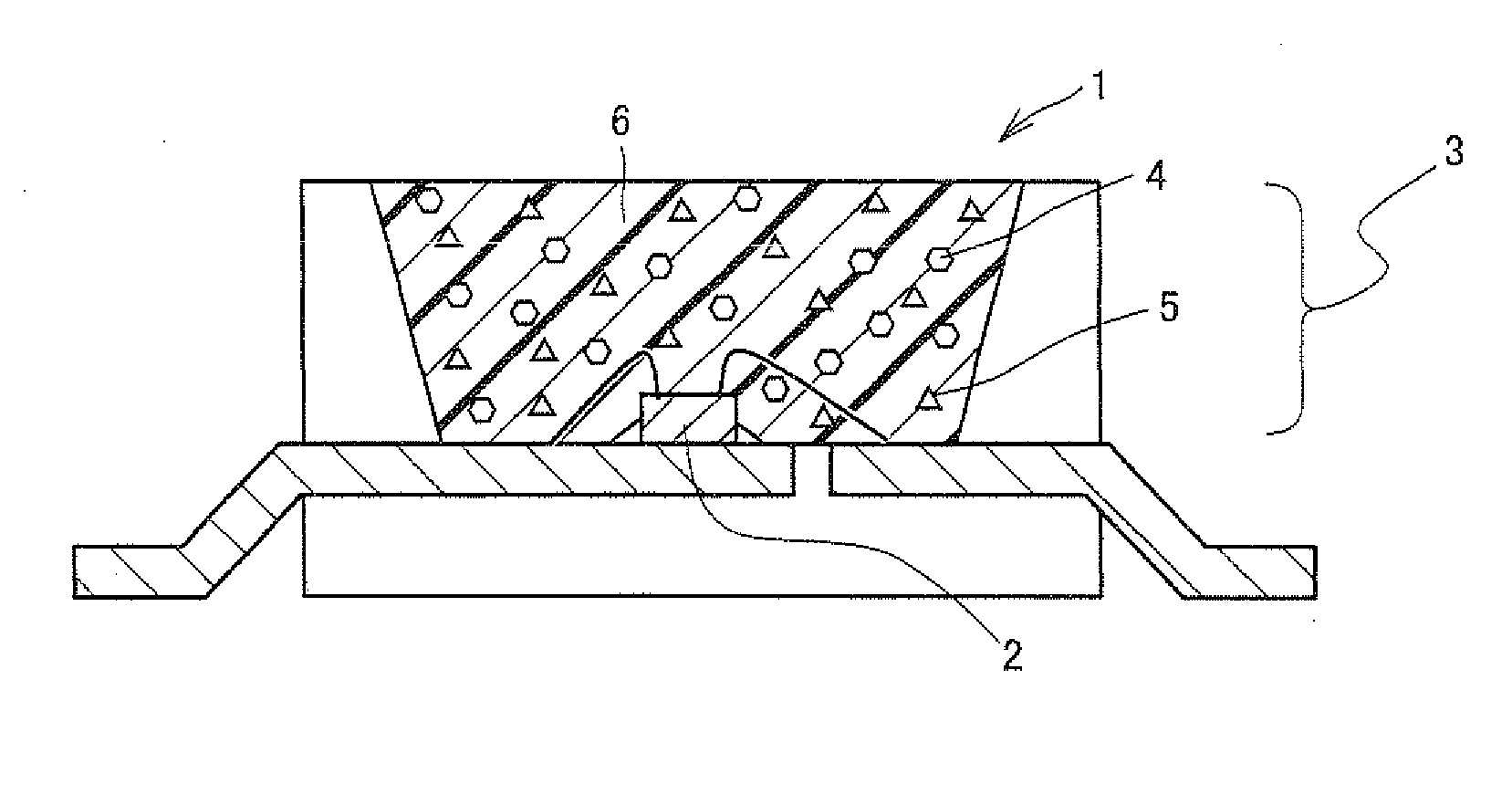
[0050]Light-emitting device 1 of the example shown in FIG. 1 was fabricated in the following manner. As light-emitting element 2, a gallium nitride (GaN)-based semiconductor having a peak wavelength at 450 nm was used, and in light converter 3, Eu0.05Si11.50Al0.50O0.05N15.95 (β-type SiAlON) was used as a green light-emitting phosphor, and K2(Ti0.99Mn0.01)F6 was used as a red light-emitting phosphor. A 30:70 (weight ratio) mixture of these green light-emitting phosphor and red light-emitting phosphor was dispersed in a predetermined resin (ratio between a resin and a phosphor was 1.00:0.25) to fabricate a light converter. In this manner, a light-emitting device of Example 1 was fabricated.

example 2

[0054]A light-emitting device was fabricated in a similar manner as Example 1 except that a gallium nitride (GaN)-based semiconductor having a peak wavelength at 440 nm was used as light-emitting element 2, 2(Ba0.70Sr0.26Eu0.04)O.SiO2 was used as a green light-emitting phosphor, and K2(Ti0.995Mn0.005)F6 was used as a red light-emitting phosphor.

examples 3 to 8

, Comparative examples 3 to 8

[0058]Light-emitting devices of Examples 3 to 8 and Comparative examples 3 to were fabricated in a similar manner as Example 1 except that combinations of a peak wavelength of a light-emitting element and phosphors as shown in the following Table 3 were used respectively, and brightness, Tc-duv and color gamut (NTSC ratio) were evaluated in a similar manner as described above. Results are also shown in Table 3.

TABLE 3Light-emittingBrightnessColor gamutelementPhosphor(relative value)Tc-duv(NTSC ratio)Example 3430 nmGreen: Eu0.30Si9.80Al2.20O0.30N15.7096.6%9500K + 0.00186.4%Red: Na2(Ti0.895Zr0.100Mn0.005)F6Comparative430 nmYellow: 2(Sr0.92Ba0.06Eu0.02)O•SiO2100.0%9500K + 0.00167.4%example 3Example 4480 nmGreen: Eu0.15Si10.00Al2.00O0.20N15.8096.0%8800K + 0.00187.9%Red: Cs2(Ti0.79Si0.20Mn0.01)F6Comparative480 nmYellow: (Y0.40Gd0.40Ce0.20)3Al5O12100.0%8800K + 0.00170.0%example 4Example 5455 nmGreen: 2(Ba0.82Sr0.15Eu0.03)O•SiO296.4%8900K + 0.00288.0%Red: Cs2(T...


PUM


Abstract

Disclosed is a light-emitting device including a light-emitting element emitting primary light, and a light converter absorbing a part of the primary light emitted from the light-emitting element and emitting secondary light having a longer wavelength than the primary light. The light converter contains a green light-emitting phosphor and a red light-emitting phosphor. The green light-emitting phosphor is composed of at least one phosphor selected from a divalent europium-activated oxynitride phosphor substantially represented by the following formula: EuaSibAlcOdNe and a divalent europium-activated silicate phosphor substantially represented by the following formula: 2(Ba1-f-gMIfEug)O.SiO2, while the red light-emitting phosphor is composed of at least one phosphor selected from tetravalent manganese-activated fluoro-tetravalent metalate phosphors substantially represented by the following formulae: MII2(MIII1-hMnh)F6 and/or MIV(MIII1-hMnh)F6. Consequently, the light-emitting device has excellent color gamut (NTSC ratio).

Description

TECHNICAL FIELD[0001]The present invention relates to a light-emitting device including a light-emitting element emitting primary light, and a light converter absorbing a part of the primary light emitted from the light-emitting element and emitting secondary light having a longer wavelength than the primary light.BACKGROUND ART[0002]A light-emitting device having a combination of a semiconductor light-emitting element and a phosphor attracts attention as a next-generation light-emitting device where low energy consumption, compact size, high brightness and wide color gamut are expected, and is actively researched and developed. As the primary light emitted from a light-emitting element, the light having a wavelength in a long wavelength UV to blue region, namely, 380 to 480 nm is usually used. Also proposed is a light converter using various phosphors suited for this application.[0003]Further, in recent years, development of a backlight for a small-sized liquid crystal display (her...

Claims


Application Information

Patent Timeline
IPC IPC(8): H01J1/63H01L33/50
CPCC09K11/0883C09K11/7734H01L33/505H05B33/14H01L33/504H01L33/502H01L2224/48091H01L2224/48247G02F1/1336H01L33/32H01L33/507H01L33/56G02F1/133614C09K11/77342C09K11/77348H01L2924/00014
Inventor MASUDA, MASATSUGUTERASHIMA, KENJI
Owner GE PHOSPHORS TECH LLC
Why Eureka
Try Eureka