Microwave antenna for wireless networking of devices in automation technology

a technology of automation technology and microwave antennas, applied in the direction of antennas, non-resonant long antennas, radiating element structural forms, etc., can solve the problems of affecting the propagation of radio waves, the inability of home and office network technology to be transferred directly to industrial production environment applications, and the dangerous movement of production installations

Inactive Publication Date: 2011-02-24
PILZ (COMPANY)
View PDF8 Cites 15 Cited by
  • Summary
  • Abstract
  • Description
  • Claims
  • Application Information

AI Technical Summary

Benefits of technology

[0006]Against this background, it is an object of the present invention to provide a low-cost microwave antenna for wireless networking of automation devices.

Problems solved by technology

However, the home and office network technology cannot be transferred directly to industrial production environment applications, because the communication requirement and the environmental conditions are different.
Typically, there are a large number of metallic objects and moving objects in factory workshops, which can severely influence the propagation of radio waves.
For example, many production installations carry out dangerous movements which must be stopped immediately when an operator approaches the installation.
However, it is not suitable for the severe environmental conditions in an industrial production installation.

Method used


Image

  • Microwave antenna for wireless networking of devices in automation technology
  • Microwave antenna for wireless networking of devices in automation technology
  • Microwave antenna for wireless networking of devices in automation technology

Examples


Embodiment Construction

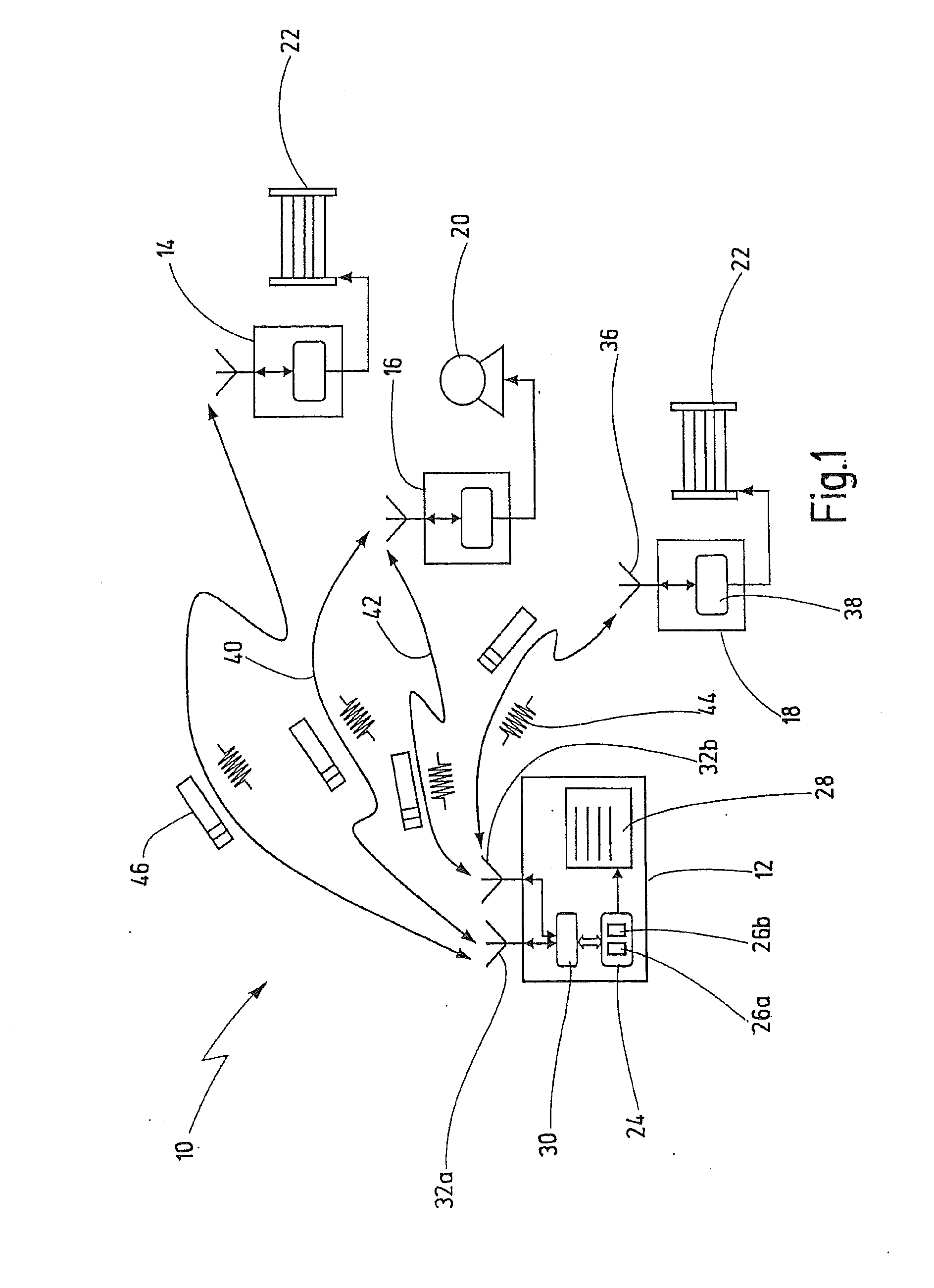
[0055]In FIG. 1, an installation where exemplary embodiments of the novel microwave antenna are used is designated overall with reference number 10.

[0056]The installation 10 has a control unit 12 and a plurality of remote I / O (input / output) units 14, 16, 18. An electrical drive 20 is connected to I / O unit 16. For example, this is a drive for a robot or some other machine for automatic processing of workpieces (not illustrated here). Drive 20 is supplied with electricity via I / O unit 16, and it can therefore be switched off by I / O unit 16. A light barrier 22 is connected to each of the I / O units 14 and 18. The light barriers 22 safeguard the robot or the electrical machine. The light barriers 22 are typical examples of sensors whose signal states are read by the control unit 12 in order to produce control signals, by means of which the drive 20 can be switched off.

[0057]The control unit 12 and the I / O units 14, 16, 18 together form a safety-relevant control system within the meaning ...


PUM


Abstract

A microwave antenna for wireless interconnection of automation devices has a first printed circuit board, on which a first conductor loop is arranged as a printed conductor track. A second printed circuit board having a second conductor loop in the form of a printed conductor track is arranged transversely with respect to the first printed circuit board. The second printed circuit board is attached to the first printed circuit board. The conductor loops are connected to a common feed connection. A bypass line connects one end of each the first and the second conductor loops.

Description

CROSS REFERENCES TO RELATED APPLICATIONS[0001]This application is a continuation of international patent application PCT / EP2008 / 009688 filed on Nov. 15, 2008 designating the U.S., which international patent application has been published in German language and claims priority from German patent application DE 10 2007 058 257.0 filed on Nov. 26, 2007. The entire contents of these prior applications are incorporated herein by reference.BACKGROUND OF THE INVENTION[0002]The present invention relates to a microwave antenna for wireless interconnection of automation devices, and in particular for networking of remote sensors, actuators and a central control unit in an automated installation.[0003]For many years, there has been an increasing desire to automate the process procedures for the industrial production of products. This is leading to increasing networking of devices and components which are involved in the production processes. Typically, these are sensors for detection of instal...

Claims


Application Information

Patent Timeline
Patent Type & Authority Applications(United States)
IPC IPC(8): H01Q3/24H01Q1/38
CPCH01Q1/38H01Q21/24H01Q9/26
Inventor INEICHEN, ALOISGODAU, THORSTEN
Owner PILZ (COMPANY)
Why Eureka
Try Eureka