
Sliding component and timepiece

a technology of sliding components and sliding components, applied in the field of sliding components, can solve the problems of affecting the efficiency of a sliding component's mechanism, the danger of its being dispersed over the entire sliding component or other components, and components will be worn early, so as to achieve the effect of easy manufacturing of sliding components, increased maintenance period, and improved wear resistan

Active Publication Date: 2011-02-24
SEIKO INSTR INC
View PDF8 Cites 6 Cited by
  • Summary
  • Abstract
  • Description
  • Claims
  • Application Information

AI Technical Summary

Benefits of technology

[0023]According to the present invention, it is possible to provide a sliding component of superior wear resistance having a lubricating oil retaining structure, and a timepiece employing this sliding component as a timepiece component to thereby achieve an increase in maintenance period. Further, according to the manufacturing method of the present invention, it is possible to easily manufacture a sliding component of superior wear resistance having a lubricating oil retaining structure.

Problems solved by technology

If the regions of these components in contact with each other lack wear resistance, these components will be worn early.
The efficiency of a mechanism using the sliding component is markedly affected by wear.
However, being a liquid, the lubricating oil does not remain at the sliding portion but there is danger of its being dispersed over the entire sliding component or to other components.

Method used


Image

  • Sliding component and timepiece
  • Sliding component and timepiece
  • Sliding component and timepiece

Examples


first embodiment

[0055]In the following, a first embodiment of the present invention will be described with reference to the drawings.

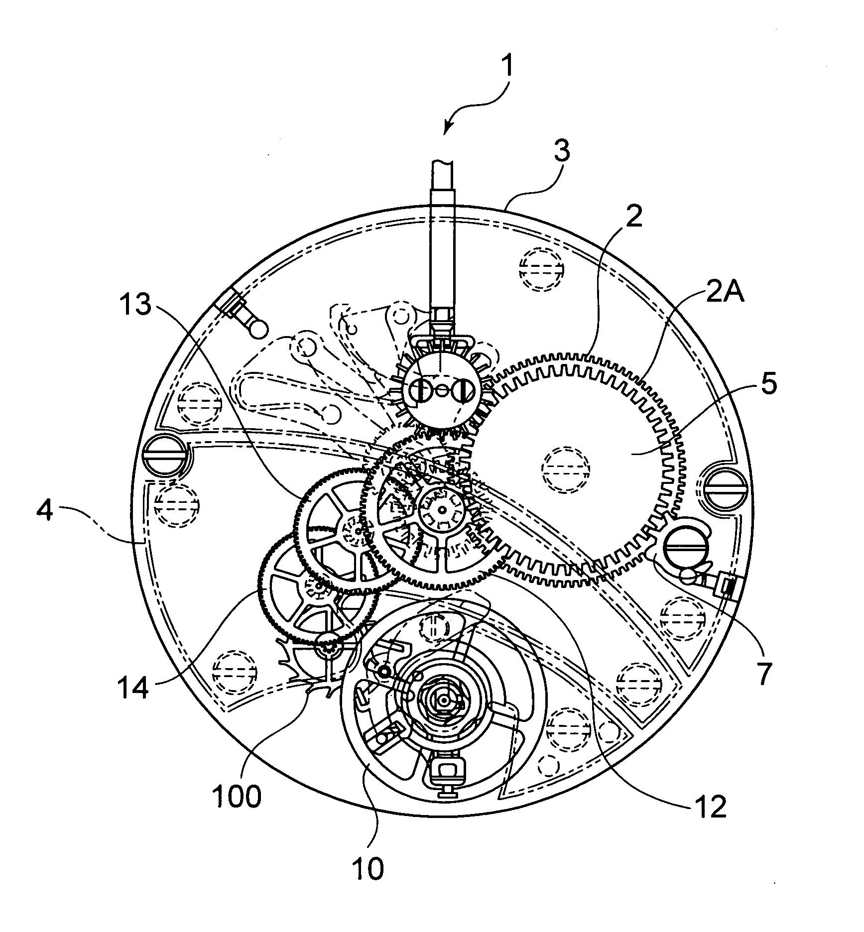
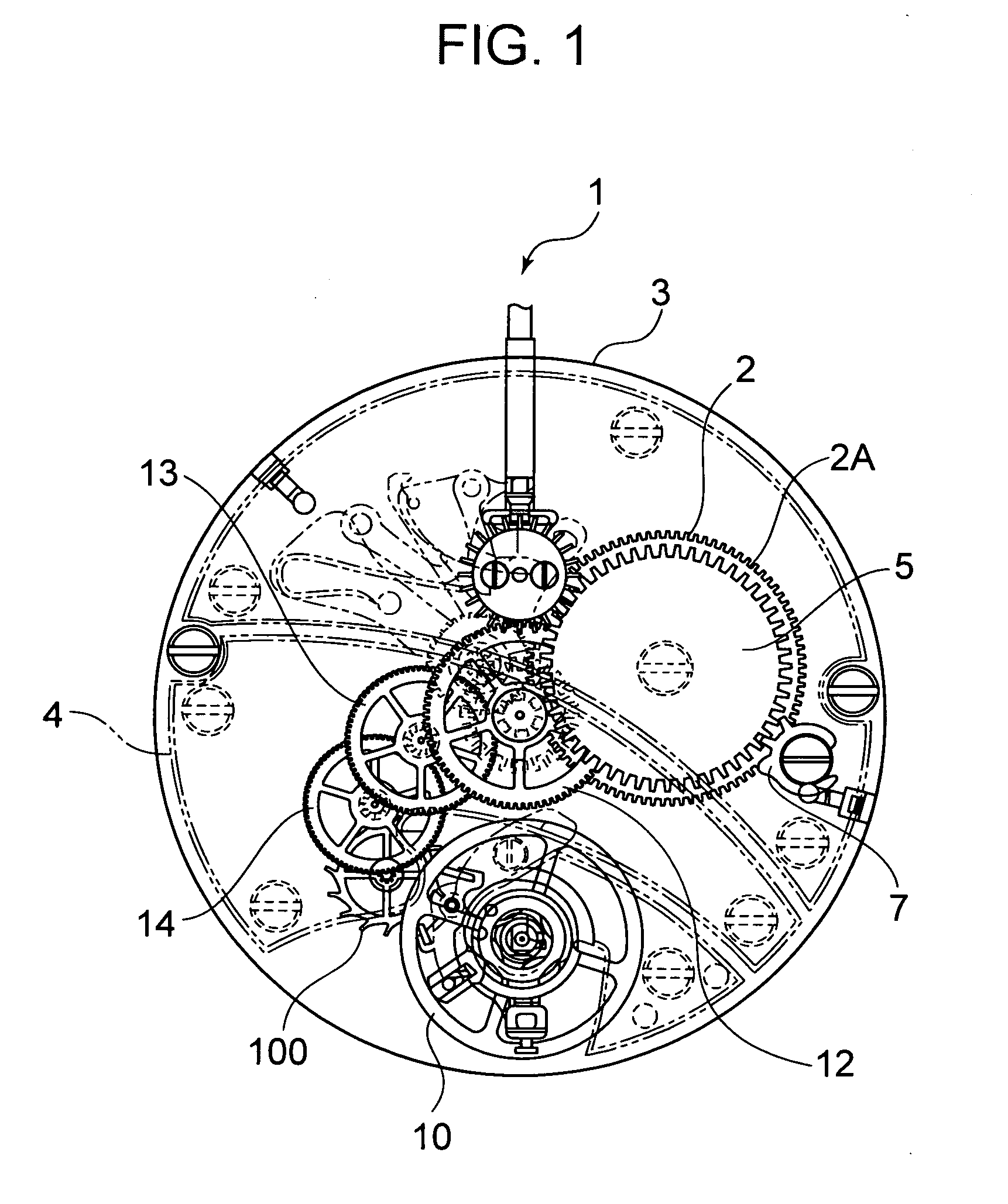
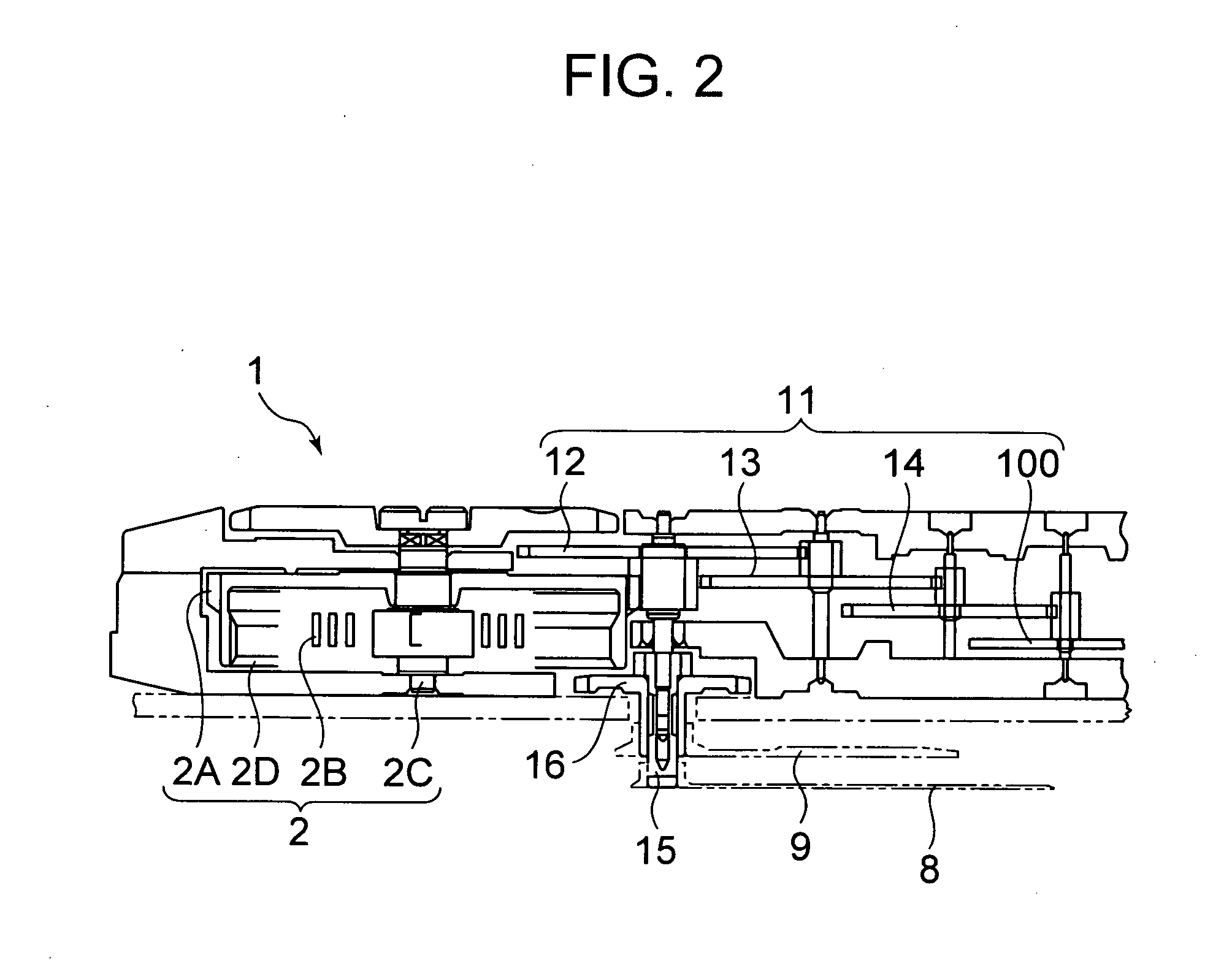
[0056]FIG. 1 is a plan view schematically showing the configuration of a movement front train wheel side of a movement of a timepiece 1, FIG. 2 is a schematic partial sectional view showing a portion extending from a barrel drum 2 to an escape wheel & pinion 100 of the timepiece 1, and FIG. 3 is a schematic partial sectional view showing a portion from the escape wheel & pinion 100 to a balance with hairspring 10 of the timepiece.

[0057]Here, the timepiece 1 is a two-hand type mechanical timepiece. However, the timepiece may also be an electronic control type mechanical timepiece, a quartz type timepiece, etc.

[0058]The timepiece 1 is equipped with a movement barrel 2 equipped with a mainspring 2B, a barrel cogwheel 2A, a barrel arbor 2C, and a barrel cover 2D. An external end of the mainspring 2B is fixed to the barrel cogwheel 2A, and an internal end thereof is fixed ...

second embodiment

[0135]FIG. 25 is a partial enlarged view of an escape wheel & pinion 700 having a structure according to the present invention. The escape wheel & pinion 700 has a multi-layer structure in which n layers (n is an integer of 4 or more) are stacked together in the thickness direction; for example, it is composed of first, third, . . . metal layers 711, 713, . . . which are formed of the same material as the first and third metal layers 121, 123 of the first embodiment and of a larger outer dimension, and second, fourth, . . . metal layers 712, 714, . . . which are, for example, formed of the same material as the second metal layer 122 and of a smaller outer dimension.

[0136]In the second embodiment described above, the effect of the first embodiment is further enhanced. In the following, a case will be described in which n is an odd number and in which the uppermost layer and the lowermost layer are metal layers of a larger outer dimension. In this case, the uppermost layer and the low...


PUM

PropertyMeasurementUnit
thickness T0aaaaaaaaaa
thickness T3aaaaaaaaaa

Abstract

The present invention aims to provide a sliding component of high wear resistance having a lubricating oil retaining structure and a structure helping to supply a lubricating oil regardless of the contact angle between itself and the mating component.There is provided a precision machinery component having at least three layers stacked together, characterized in that a portion substantially parallel to the stacking direction has a sliding portion coming into contact with another component, and that at least a part of the sliding portion has a recess.

Description

TECHNICAL FIELD[0001]The present invention relates to a sliding component used as a timepiece component such as a cogwheel or a bearing.BACKGROUND ART[0002]As a method of manufacturing a sliding component of high dimensional precision such as a small cogwheel, there is employed a technique combining photolithography and electroforming (See, for example, Patent Document 1). A sliding component involves generation of friction due to a mutual action between itself and a component held in contact therewith. If the regions of these components in contact with each other lack wear resistance, these components will be worn early. The efficiency of a mechanism using the sliding component is markedly affected by wear. In view of this, in order to achieve an increase in wear resistance, a lubricating oil is used. However, being a liquid, the lubricating oil does not remain at the sliding portion but there is danger of its being dispersed over the entire sliding component or to other components...

Claims


Application Information

Patent Timeline
Patent Type & Authority Applications(United States)
IPC IPC(8): B32B3/02B32B3/30G03F7/20
CPCG04D3/0033Y10T428/24488G04D3/0069G04B15/14Y10T428/24612
Inventor SATO, MIEIMIYOSHI, NATSUKIKISHI, MATSUOAMANO, NAOKINIWA, TAKASHI
Owner SEIKO INSTR INC
Learn More