
Cardiac tissue retractor with associated valve cusp depressor

Inactive Publication Date: 2011-02-24
CORONEO
View PDF14 Cites 34 Cited by
  • Summary
  • Abstract
  • Description
  • Claims
  • Application Information

AI Technical Summary

Benefits of technology

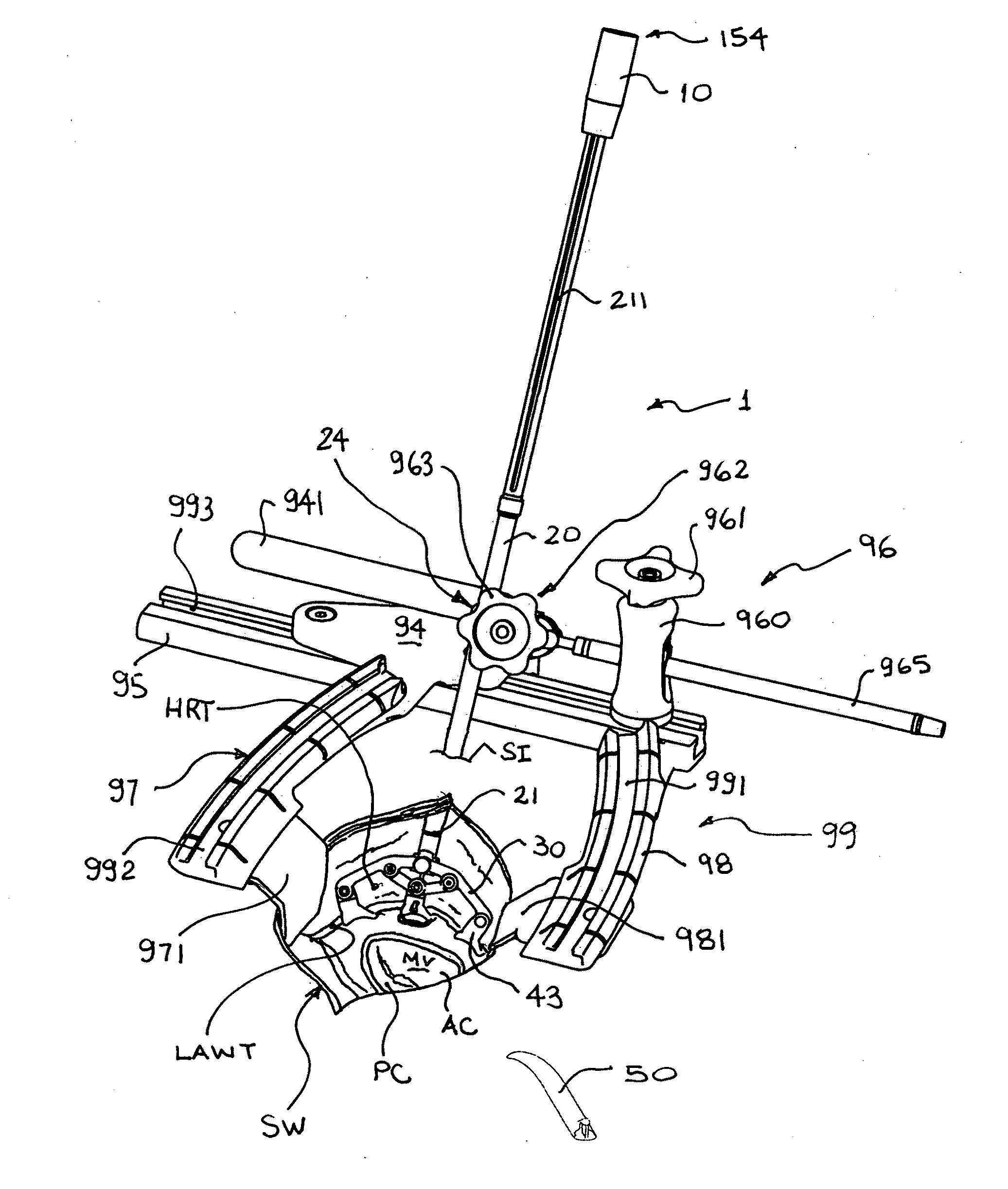
[0011]It is a further object of the present invention to be able to mount a cardiac tissue retractor to a stable surgical platform in order to retract a cardiac tissue so as to obtain proper surgical access to a target cardiac valve being operated on, and in situ, during use, operatively couple a valve cusp depressor to said cardiac tissue retractor, and secure the position of said cusp depressor to said cardiac tissue retractor, thus avoiding the need to independently and separately mount said cusp depressor to said surgical platform through a separate surgical set-up.

Problems solved by technology

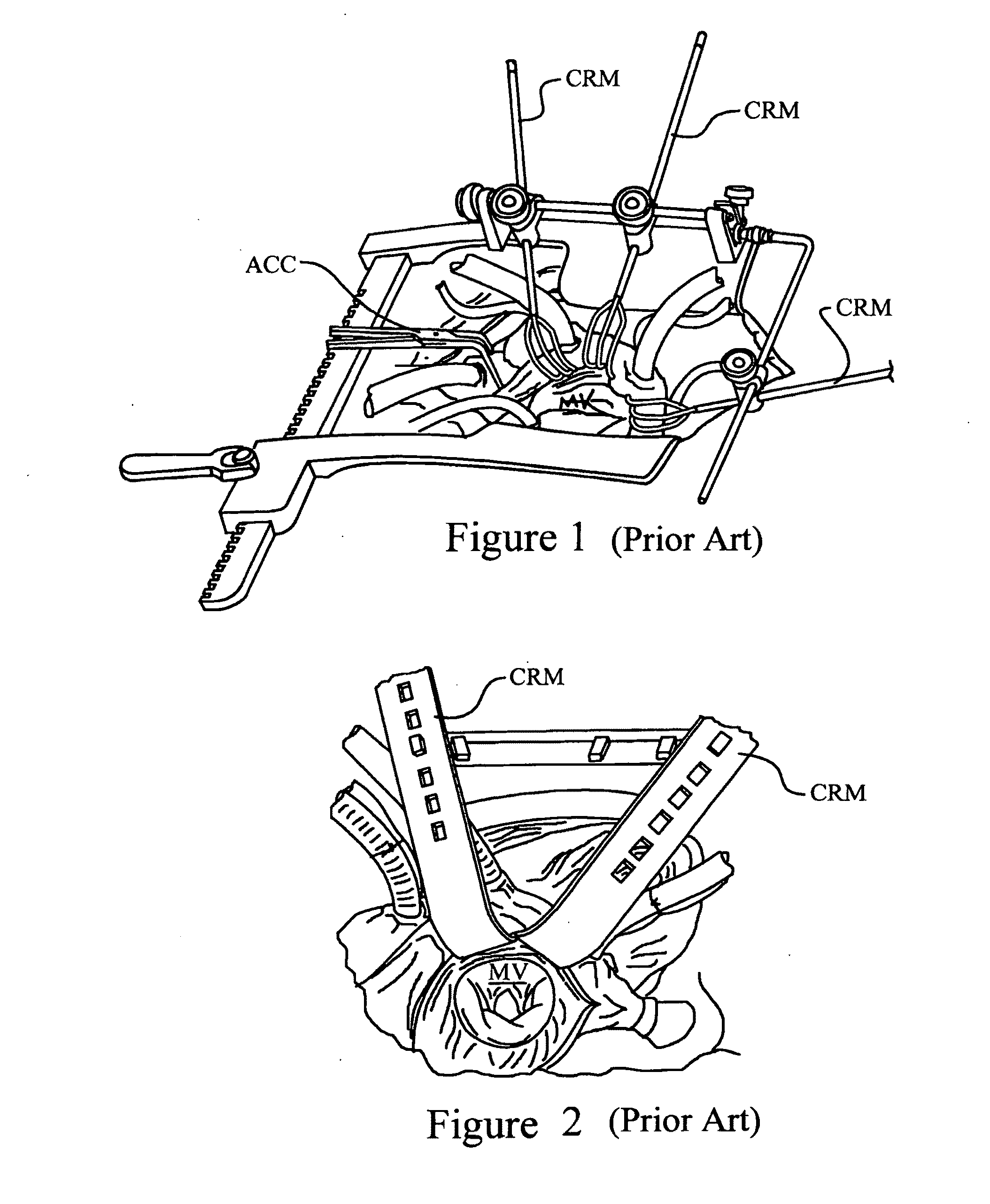
Having an independently mounted atrial retractor, and requiring a surgical assistant having to depress a target valve cusp with a makeshift cusp depressor through a limited access port in patient's thorax, without encumbering the surgeon's vision or access, makes such minimally invasive procedures impractical or in some cases impossible to achieve, given the relatively smaller size of the surgical window.

Method used


Image

  • Cardiac tissue retractor with associated valve cusp depressor
  • Cardiac tissue retractor with associated valve cusp depressor
  • Cardiac tissue retractor with associated valve cusp depressor

Examples


Embodiment Construction

[0033]The invention will be described in the context of a cardiac valve surgery performed on the mitral valve of the patient. It is understood that the concepts and principles of the invention may be applied to tissue retracting apparatus used to perform cardiac surgery on the other cardiac valves (i.e. pulmonary, tricuspid, and aortic) without departing from the spirit of the invention.

[0034]The heart is contained within a patient's thorax or thoracic cavity, and is located beyond a structural ribcage. The heart includes a number of internal cavities through which blood flows and which are associated with a heart valve. Included in these internal cavities are the heart chambers (left atrium, right atrium, left ventricle, right ventricle). Each of the heart chambers is delimited by a number of chamber-defining walls and inner chamber partitions or septal walls. As well, each of the heart chambers is delimited by at least one cardiac valve to control passage of blood flow through the...


PUM


Abstract

A tissue retracting apparatus for use in cardiac surgery having a first tissue retracting member configured and sized to retract a cardiac tissue of the patient's heart in a manner to obtain surgical access to a target heart valve located within an internal heart cavity, and a second tissue retracting member configured and sized to retract, depress or displace a valve cusp tissue of the target heart valve in a manner to obtain surgical access beyond the target heart valve. In use, the second tissue retracting member is operatively couplable to the first retracting member, so that the first and second retracting members cooperate together to collectively allow the simultaneous retraction of both (i) a cardiac tissue of the patient's heart, and (ii) a valve cusp of the target valve while a surgical intervention can be carried out on either the target heart valve or a subvalvular structure of said target heart valve.

Description

[0001]This application claims the benefits of United States Provisional Patent Application 61 / 213,960 filed Aug. 3, 2009.FIELD OF THE INVENTION[0002]The present invention relates to the field of cardiac surgical instruments and more specifically, to cardiac tissue retractors that are adapted for use in valve surgery to retract a portion of a patient's heart in order to access a target heart valve found therein, said tissue retractor also provided with a means or member that is configured to depress, displace or retract a valve cusp of said target valve during said use.BACKGROUND OF THE INVENTION[0003]Current tissue retractors, especially in cardiac surgery, are typically of a fixed geometry. They are most commonly configured at the tissue-retracting end with either a “basket” type configuration made from spaced apart wire frame members, or with an uninterrupted and shaped tissue contacting surface or blade that engages the cardiac or heart tissue to be retracted. These retractors ar...

Claims


Application Information

Patent Timeline
IPC IPC(8): A61B1/32A61B19/00
CPCA61B2019/5206A61B17/0206A61B2090/306
Inventor PAOLITTO, ANTHONYVALENTINI, VALERIO
Owner CORONEO
Learn More