Network control system

a network control and control system technology, applied in the field of network control systems, can solve the problems of increasing the cost of fabrication and maintenance, increasing the cost of plant control system fabrication, and the past four plant control systems, so as to improve the efficiency of network transfer, reduce the cost, and simplify the system configuration

Active Publication Date: 2011-02-24
TOSHIBA MITSUBISHI-ELECTRIC IND SYST CORP +1
View PDF5 Cites 36 Cited by
  • Summary
  • Abstract
  • Description
  • Claims
  • Application Information

AI Technical Summary

Benefits of technology

[0028]The present invention has been devised in view of the problems described, and it is an object of the present invention to provide a network control system with a simplified system configuration leading to a reduced cost, allowing for an enhanced efficiency in network transfer, an optimized transfer data, and a facilitated engineering.

Problems solved by technology

However, the plant control system in the past had four problems, as follows.
As a first problem, there was an increase in cost of fabrication as well as in cost of maintenance due to complexity of system configuration.
That is, for transfer of data between sub-networks, there was needed provision of data transfer systems DT104, DT105, and DT106 and a superordinate network N 110, with an increased cost in fabrication of plant control system.
Further, as a problem in an entirety of plant control system, there was a failure rate increased as the system number increased, with increased expenses for the maintenance.
As a second problem, there was a decrease in transfer rate of data.
As a result, the data transfer rate was reduced, as a problem.

Method used


Image

  • Network control system
  • Network control system
  • Network control system

Examples


first embodiment

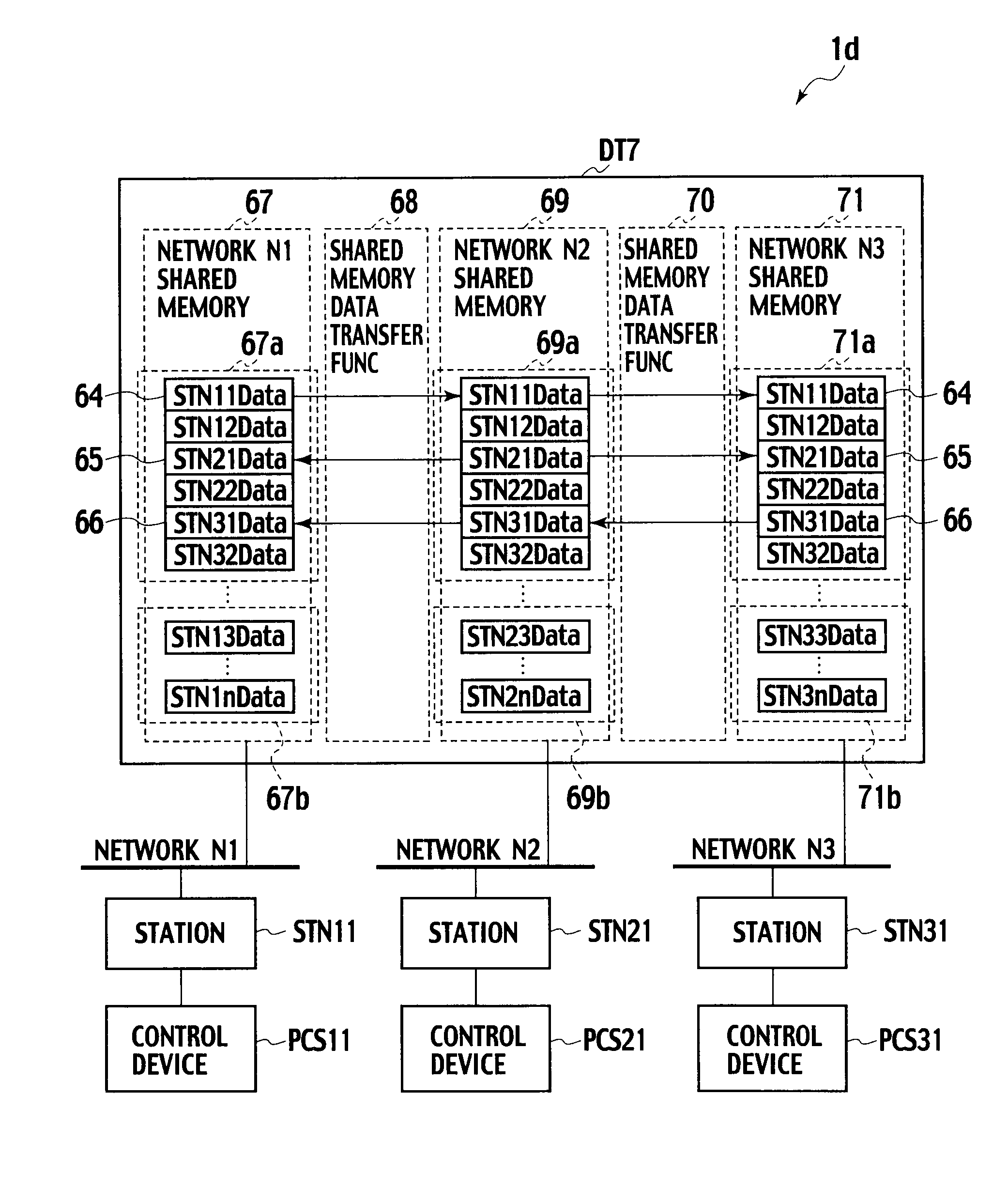
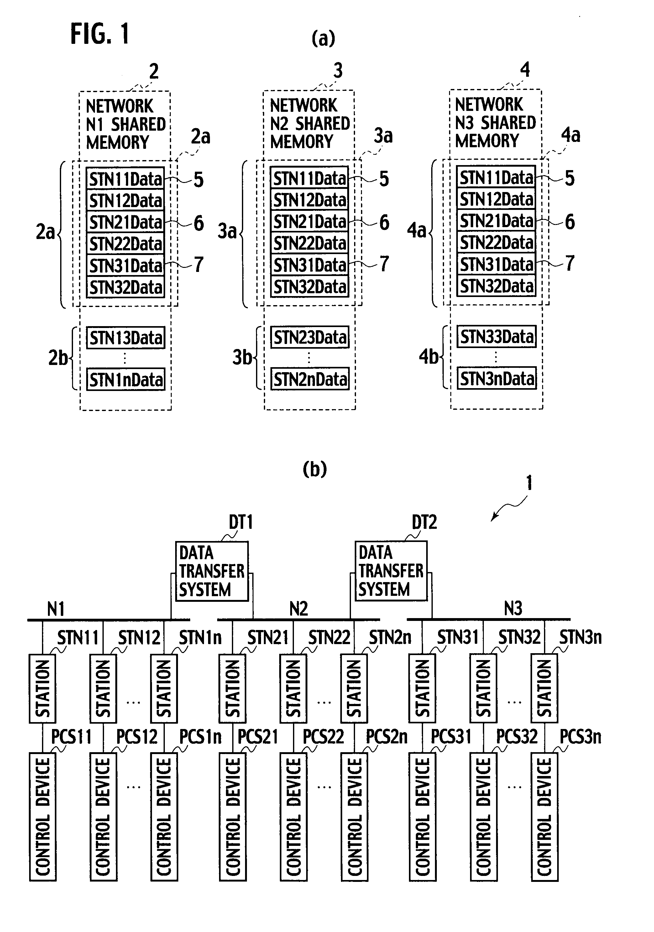
[0049]FIG. 1(a) is an explanatory diagram showing internal configurations of shared memories in a network control system according to a first embodiment of the present invention, and FIG. 1(b) is a configuration diagram showing a system configuration of the network control system according to the first embodiment of the present invention.

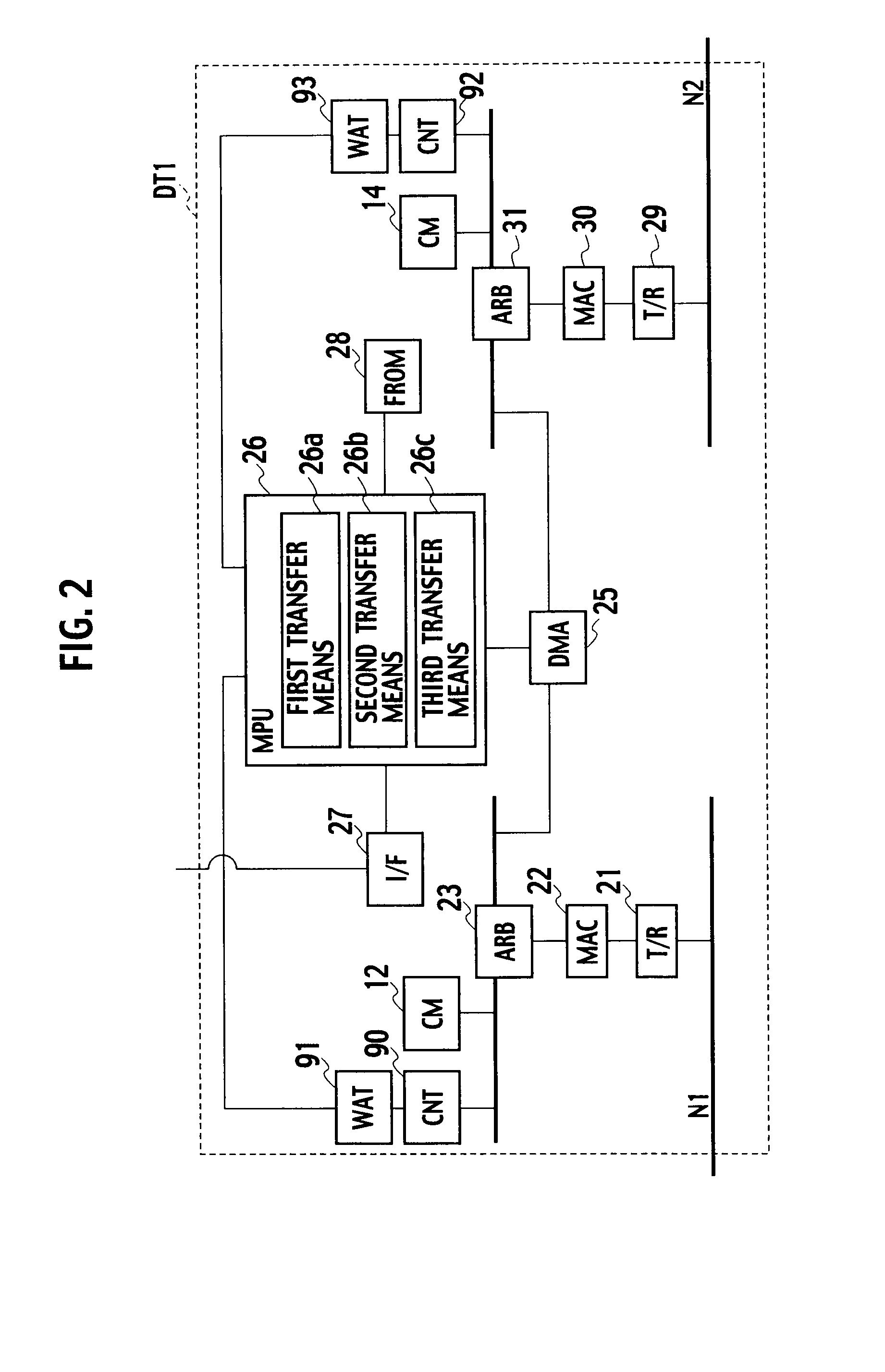
[0050]As shown in FIG. 1(b), the network control system 1 according to the first embodiment includes a data transfer system DT1, a data transfer system DT2, a set of n stations STN11 to STN1n, a set of n stations STN21 to STN2n, and a set of n stations STN31 to STN3n. The data transfer system DT1 and stations STN11 to STN are interconnected through a network N1. Between the data transfer system DT1 and stations STN21 to STN2n, as well as between the data transfer system DT2 and the stations STN21 to STN2n, there are interconnections through a network N2. The data transfer system DT2 and stations STN31 to STN3n are interconnected through a network N3...

second embodiment

[0122]FIG. 5(a) is an explanatory diagram showing internal configurations of shared memories in a network control system according to a second embodiment of the present invention, and FIG. 5(b) is a configuration diagram showing a system configuration of the network control system according to the first embodiment of the present invention.

[0123]As shown in FIG. 5(b), the network control system 1b according to the second embodiment includes a data transfer system DT5 and a data transfer system DT6, substituting for the data transfer systems DT1 and DT2 as constituent parts of the network control system 1 according to the first embodiment, respectively.

[0124]Further, there are networks N1 to N3 including stations having their shared memories each divided into sub-areas, by orders of priority of shared data, as illustrated in FIG. 5(a). More specifically, in the network N1, each shared memory 50a is divided into classes of transfer rate as set up in three ranks being a high transfer ra...

third embodiment

[0180]Description is now made of a network control system 1c according to a third embodiment.

[0181]FIG. 8 is an explanatory diagram showing an example of global shared memory area 11 set up as an array of consecutive areas from a beginning address.

[0182]As illustrated in FIG. 8, there is an array of consecutive areas set as a global shared memory area 11, to thereby implement a data transfer system between networks with an increased data transfer rate. In this respect, simply with an enabled setup of an array of consecutive areas, there might appear inconveniences in extension or modification of global shared memory area 11 by users.

[0183]To this point, according to the third embodiment, the network control system 1c is configured for adaptation to set up a global shared memory area 11 using an arbitrary subset of a set of areas in a network shared memory space, in a voluntary manner.

[0184]FIG. 9 is a configuration diagram showing a system configuration of the network control system...


PUM


Abstract

First and second stations have first and second memory elements (2, 3) for storing first and second shared data, respectively, and a data transfer system (DT1) includes third and fourth memory elements (CM 12, CM 14) for storing third and fourth shared data, respectively, first and second transfer period determiner (CNT 90, CNT 92), a first transfer element (26a) working to operate in accordance with the first transfer period to have the second shared data stored in the fourth memory element (CM 14) and operate in accordance with the second transfer period to have the first shared data stored in the third memory element (CM 12), a second transfer element (26b) working for transfer of shared data between the fourth memory element (CM 14) and the third memory element (CM 12), and a third transfer element (26c) working to operate in accordance with the second transfer period to have the fourth shared data stored in the second memory element (3) and operate in accordance with the first transfer period to have the third shared data stored in the first memory element (2).

Description

TECHNICAL FIELD [0001]The present invention relates to a network control system widely used for control of industrial systems, such as those in, among others, iron and steel making plants or paper making plants, FA fields including assembly operations such as in automobile industries, PA fields such as for chemical plants, or water supply and sewerage systems or other public systems.BACKGROUND ART[0002]For control of plant equipments, there have been typical plant control systems including those configured with control devices interconnected through a network to implement data transfer between control devices via the network. Also, there have been plant control systems for large-scale plants, including those configured with control devices increased in number and accompanied by a set of superordinate networks hierarchically architected to implement data transfer between networks.[0003]Still also, there has been use of a set of sub-network repeaters described in a patent literature 1...

Claims


Application Information

Patent Timeline
Patent Type & Authority Applications(United States)
IPC IPC(8): G06F15/16G06F15/167G05B19/418H04L12/28
CPCG05B2219/31124G05B19/41855Y02P90/02
Inventor NOJIMA, AKIRAUMEDA, YUUJI
Owner TOSHIBA MITSUBISHI-ELECTRIC IND SYST CORP
Why Eureka
Try Eureka