Structure for securing solar cell modules and frame and securing member for solar cell modules

a technology for solar cells and structures, applied in the direction of heat collector mounting/support, pv power plants, light and heating apparatus, etc., can solve the problems of reducing the impaction of the frame with respect to the securing member, and reducing the workability of the frame. , to achieve the effect of improving workability and increasing the support strength of the securing member for the fram

Active Publication Date: 2011-03-03
YANEGIJUTSUKENKYUJO CO LTD
View PDF3 Cites 44 Cited by
  • Summary
  • Abstract
  • Description
  • Claims
  • Application Information

AI Technical Summary

Benefits of technology

[0025]According to the present invention, the frames of solar cell modules can be engaged horizontally on both sides of the shaft portions of the securing members, and impaction of frames engaged on the same side of the shaft portions as the securing units is retrained by the inner protrusions. Since a predetermined amount of space can be formed between the shaft portions and the frames on the same side of the shaft portions as the securing units, the frames of adjacent solar cell modules can be prevented from being brought into direct contact with one another, and the same effects as above can be achieved. Any solar cell modules having the frames that can be engaged between the base units and the top portions can be secured to the predetermined supporting member, and accordingly, the securing members according to the present invention can cope with conventional solar cell modules.
[0026]As described above, a predetermined amount of space can be formed between the shaft portions and the frames on the sa

Problems solved by technology

However, the frames on the ridge side support the solar cell modules only by the engagement between the engaging protrusions of the frames and the engaged protrusions of the securing members.
As a result, the supporting strength of the frames on the ridge side becomes weaker than that of the frames on the eaves side.
Therefore, if the head portions of screws or the like protrude

Method used


Image

  • Structure for securing solar cell modules and frame and securing member for solar cell modules
  • Structure for securing solar cell modules and frame and securing member for solar cell modules
  • Structure for securing solar cell modules and frame and securing member for solar cell modules

Examples


Embodiment Construction

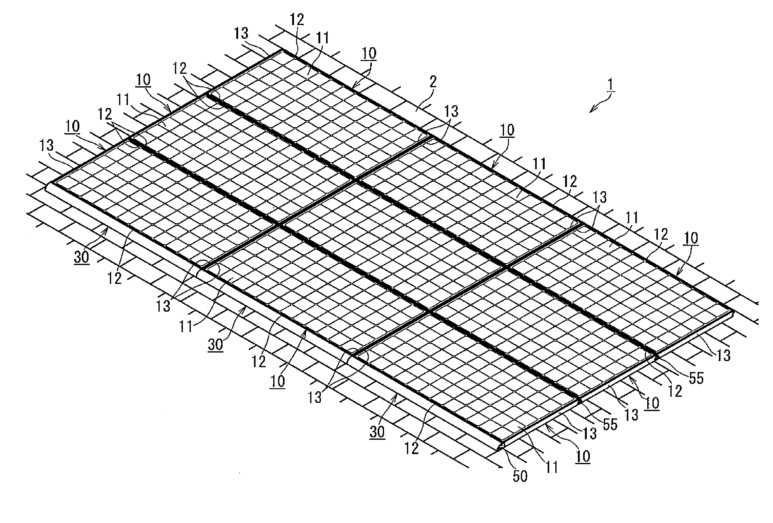
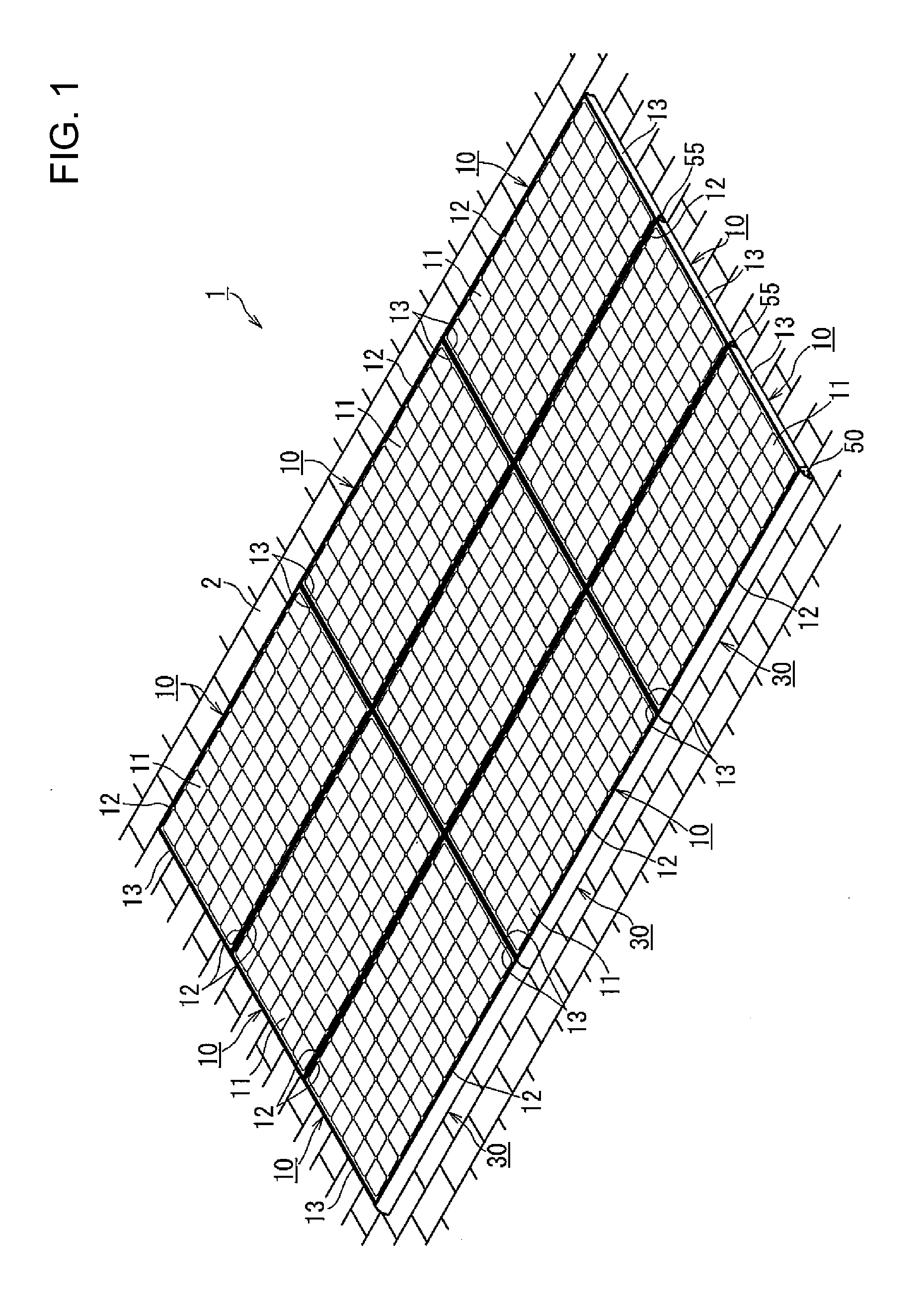
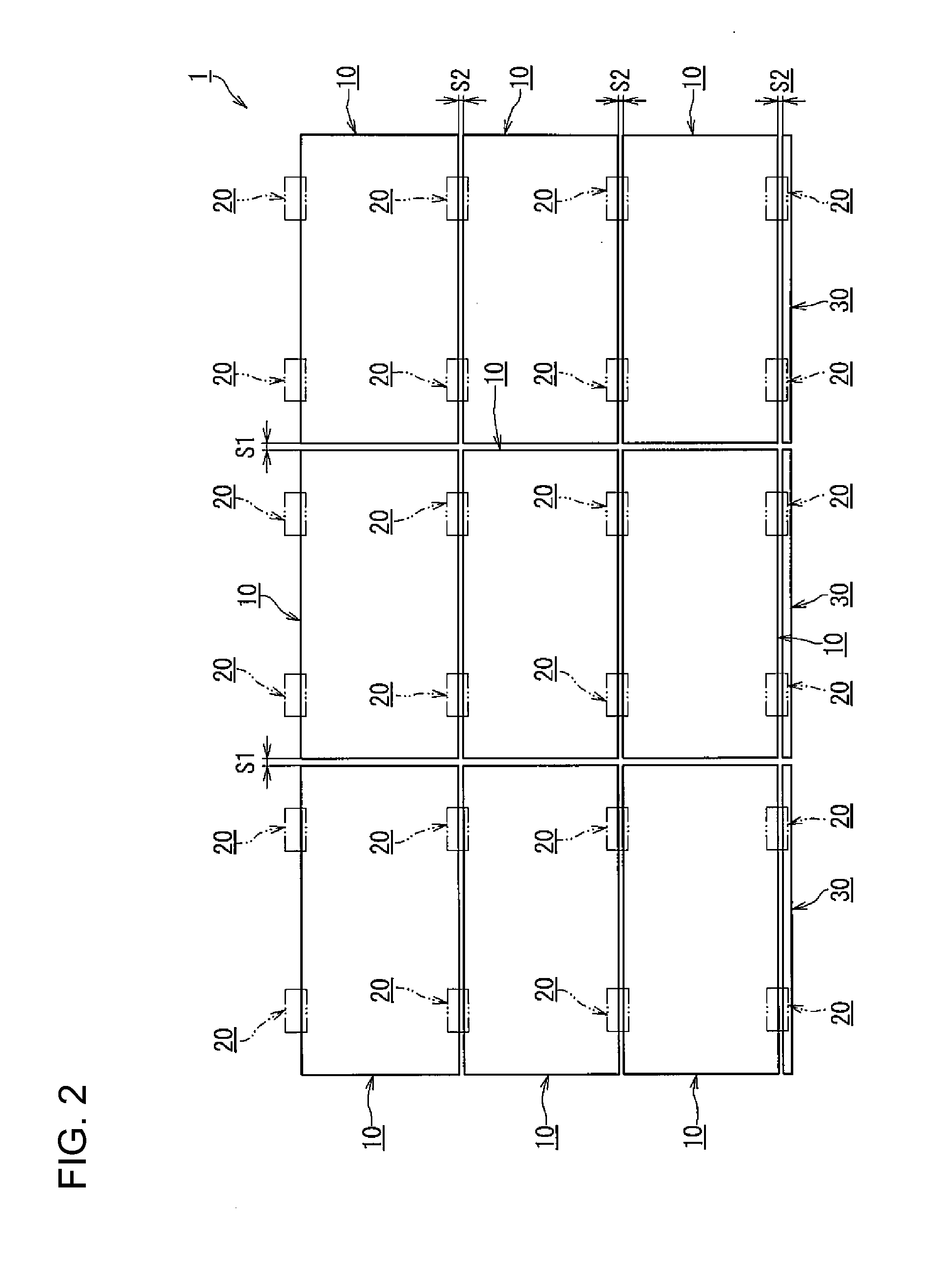
[0039]Referring to FIGS. 1 through 11, a structure for securing solar cell modules, and frames and securing members for the solar cell modules are described in detail as an embodiment of the present invention. FIG. 1 is a perspective view of an entire solar photovoltaic system to which the structure for securing solar cell modules and the frames and the securing members for the solar cell modules as an embodiment of the present invention are applied. FIG. 2 is a schematic plan view of the solar photovoltaic system of FIG. 1. FIG. 3 is a cross-sectional side view of part of the solar photovoltaic system of FIG. 1. FIG. 4 is an enlarged cross-sectional side view of the essential parts of the solar photovoltaic system of FIG. 1. FIG. 5 is a schematic exploded perspective view of each main component of the solar photovoltaic system of FIG. 1. FIG. 6(A) is an end elevational view of an ornamental cover used for the solar photovoltaic system of FIG. 1. FIG. 6(B) is an end elevational view...


PUM


Abstract

The present invention provides a solar cell module securing structure capable of securing solar cell modules without any trouble even when there is a change in temperature or the like, and also provides frames and securing members for the solar cell modules.
A contact portion (12e) of each of the first frames (12) of solar cell modules (10) engaged on the opposite side of a shaft portion (22) of each securing member (20) securing a solar cell module (10) to a supporting member (2) from securing units (21a) can be fastened to the shaft portion (22) with engaging screws (4) through a void (24b) from the side of the securing units (21a). The contact portion (12e) of each of the first frames (12) engaged on the side of the securing units (21a) are brought into contact with the outer end portion (24a) of each inner protrusion (24), to restrict impaction of the first frames (12). With this arrangement, a predetermined amount of space is formed between the contact portions (12e) and the shaft portions (22), and a predetermined amount of space is formed between the facing upper side faces (12a) of the first frames (12) engaged with both sides of each of the shaft portions (22).

Description

CROSS REFERENCE TO RELATED APPLICATIONS[0001]This application claims the benefit of priority upon International Patent Application PCT / JP2009 / 062499, filed Jul. 9, 2009, of which full contents are incorporated herein by reference.BACKGROUND OF THE INVENTION[0002]1. Field of the Invention[0003]The present invention relates to a solar cell module securing structure for securing solar cell modules each having the peripheral sides of a solar cell panel supported by a frame to a predetermined supporting member such as a roof or a wall surface through the use of securing members, and also relates to the frames and the securing members for the solar cell modules.[0004]2. Description of the Related Art[0005]In preceding patent applications, the applicant suggests structures with which solar cell modules can be placed on a roof or the like via securing members that can be engaged with the frame bodies of the solar cell modules perpendicularly to the surface of the frame bodies and can slide ...

Claims


Application Information

Patent Timeline
IPC IPC(8): E04D13/18E04B1/38
CPCF24J2/5211F24J2/5245F24J2/526F24J2002/4665H02S20/23F24J2002/5215F24J2002/5281Y02B10/12Y02E10/47F24J2002/467F24S25/61F24S2025/014F24S25/20F24S2025/6007F24S25/65F24S2025/801F24S2025/6004Y02E10/50Y02B10/10
Inventor KOBAYASHI, SHUICHI
Owner YANEGIJUTSUKENKYUJO CO LTD
Why Eureka
Try Eureka