Method for evaluating degradation of a particulate matter sensor

Active Publication Date: 2011-03-03
FORD GLOBAL TECH LLC
View PDF13 Cites 60 Cited by
  • Summary
  • Abstract
  • Description
  • Claims
  • Application Information

AI Technical Summary

Benefits of technology

[0003]Particulate matter may be present in the exhaust of some engines, diesel engines for example. Vehicle tailpipe emissions may be reduced by installing particulate filters and particulate matter sensors in vehicle exhaust systems. One pa

Problems solved by technology

The above-mentioned sensor may under some conditions experience degradation.
However, it may be difficult to establish sensor degradation because the particulate sensor exhibits a high resistanc

Method used


Image

  • Method for evaluating degradation of a particulate matter sensor
  • Method for evaluating degradation of a particulate matter sensor
  • Method for evaluating degradation of a particulate matter sensor

Examples


Embodiment Construction

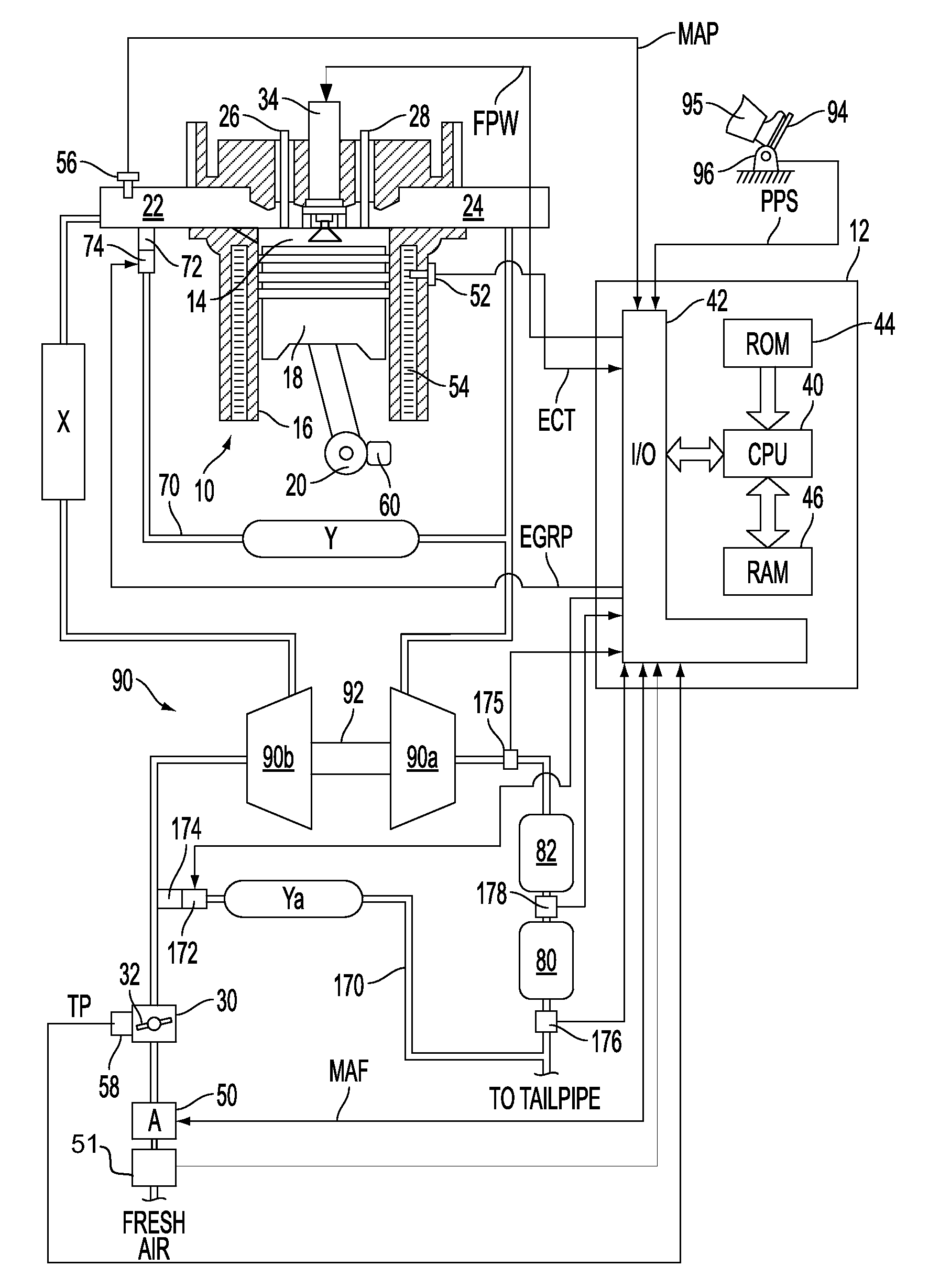
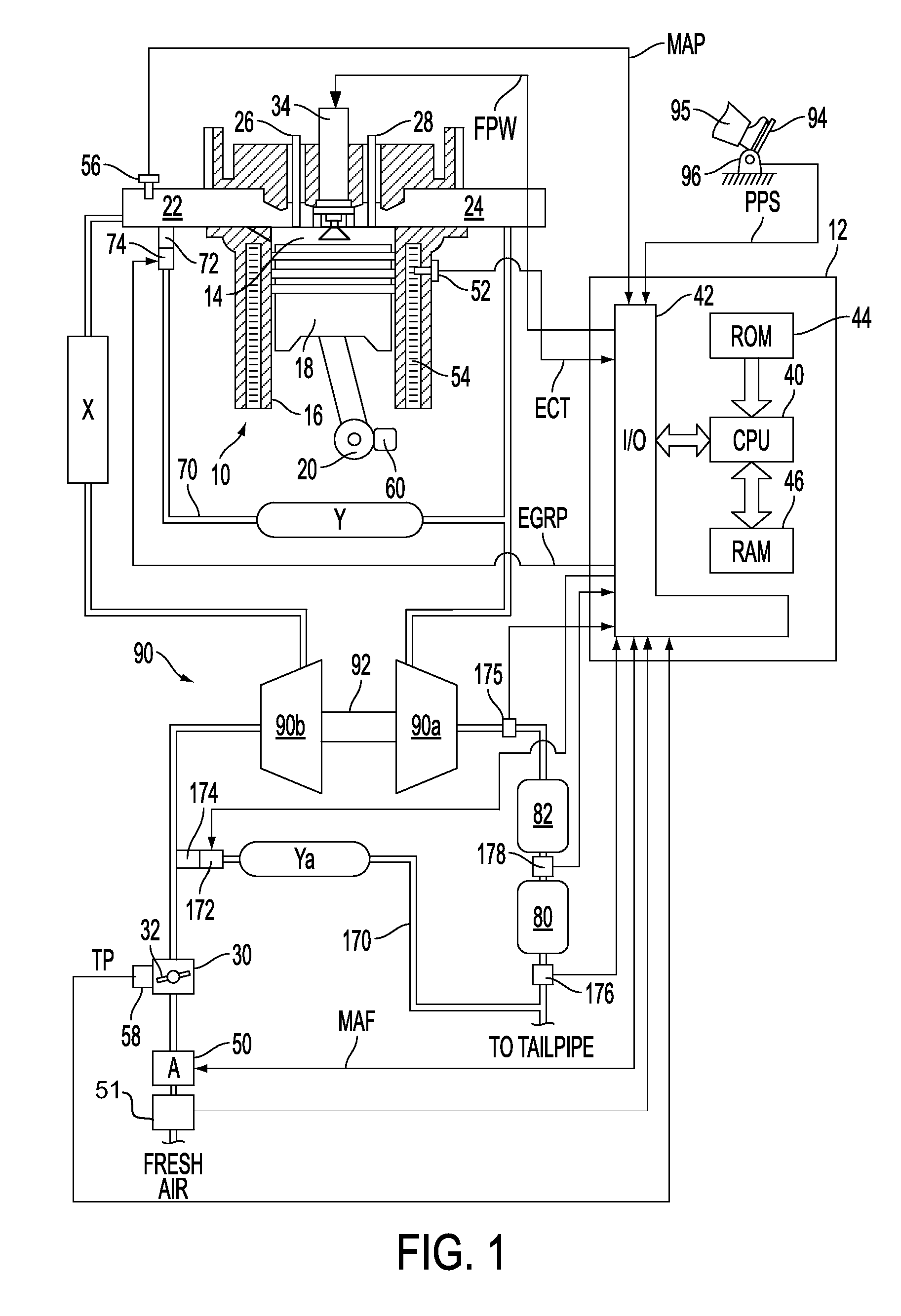
[0017]FIG. 1 shows an exemplary embodiment of an engine system generally at 10. Specifically, internal combustion engine 10 comprises a plurality of cylinders, one cylinder of which is shown in FIG. 1. Engine 10 is controlled by electronic engine controller 12. Engine 10 includes combustion chamber 14 and cylinder walls 16 with piston 18 positioned therein and connected to crankshaft 20. Combustion chamber 14 communicates with an intake manifold 22 and an exhaust manifold 24 via respective intake valve 26 and exhaust valve 28.

[0018]Intake manifold 22 communicates with throttle body 30 via throttle plate 32. In one embodiment, an electronically controlled throttle can be used. In one embodiment, the throttle is electronically controlled to periodically, or continuously, maintain a specified vacuum level in intake manifold 22. Alternatively, throttle body 30 and throttle plate 32 may be omitted.

[0019]Combustion chamber 14 is also shown having fuel injector 34 coupled thereto for deliv...


PUM


Abstract

A system for improving operation of an engine having a particulate matter sensor is presented. The system may be used to improve engine operation during cold starts especially under conditions where water vapor or entrained water droplets are present in vehicle exhaust gases. In one embodiment, degradation of a particulate matter sensor is indicated after a temperature of a substrate of the particulate matter sensor exceeds a threshold temperature and an output of the particulate matter sensor is below a threshold value.

Description

CROSS-REFERENCE TO RELATED APPLICATIONS[0001]This application claims priority from U.S. Provisional Patent Application No. 61 / 239,381, entitled “SYSTEM FOR AN ENGINE HAVING A PARTICULATE SENSOR,” filed Sep. 2, 2009, the disclosure of which is hereby incorporated by reference in its entirety and for all purposes.FIELD[0002]The present description relates to a system for improving operation of an engine having a sensor and a particulate filter. The system may be particularly useful for improving emissions of engines having particulate matter sensors.BACKGROUND AND SUMMARY[0003]Particulate matter may be present in the exhaust of some engines, diesel engines for example. Vehicle tailpipe emissions may be reduced by installing particulate filters and particulate matter sensors in vehicle exhaust systems. One particular type of particulate sensor senses particulate matter by electrodes separated by a dielectric gap. When particulate matter bridges the gap between electrodes, the resistanc...

Claims


Application Information

Patent Timeline
IPC IPC(8): F01N11/00F01N3/023F01N3/10F02D43/00
CPCF01N2560/05F02D41/1494G01N33/0006G01N15/0656Y02T10/40F02D41/222
Inventor ZAWACKI, GARRY ANTHONYNOVAK, ROBERT F.TERAN, JR., ROBERTOWEBER, DAVE CHARLESVAN NIEUWSTADT, MICHIEL J.HOPKA, MICHAELRUONA, WILLIAM CHARLES
Owner FORD GLOBAL TECH LLC
Why Eureka
Try Eureka