
Exhaust gas purification apparatus

a technology of exhaust gas purification and exhaust gas, which is applied in mechanical equipment, machines/engines, separation processes, etc., can solve the problems of gas purification, exhaust gas aftertreatment devices disclosed in the above publication do not have a sufficient exhaust gas purification performance, and the reduction of nox cannot be performed under a lower temperatur

Inactive Publication Date: 2011-03-03
TOYOTA IND CORP
View PDF5 Cites 14 Cited by
  • Summary
  • Abstract
  • Description
  • Claims
  • Application Information

AI Technical Summary

Benefits of technology

[0007]In accordance with the present invention, an exhaust gas purification apparatus includes an exhaust gas passage, a first oxidation catalyst, a selective catalytic reduction catalyst, an oxidation-reduction catalyst and a urea water supply device. Exhaust gas is flowed through the first oxidation catalyst. The first oxidation catalyst is disposed in the exhaust gas passage. The selective catalytic reduction catalyst is disposed downstream of the first oxidation catalyst. The oxidation-reduction catalyst is disposed downstream of the selective catalytic reductio

Problems solved by technology

Thus, in the exhaust gas aftertreatment device, the reduction of NOx cannot be performed under a lower temperature where reduction activity of the urea SCR catalyst is decreased.
Therefore, the exhaust gas aftertreatment device disclosed in the above Publication does not have a sufficient exhaust gas purification performance by reducing NOx under a lower temperature of exhaust gas where the temperature of the urea SCR catalyst is decreased.
The exhaust gas aftertreatment device has a problem in that gas purification can be achieved partially only under a high temperature of exhaust gas.

Method used


Image

  • Exhaust gas purification apparatus
  • Exhaust gas purification apparatus
  • Exhaust gas purification apparatus

Examples


Embodiment Construction

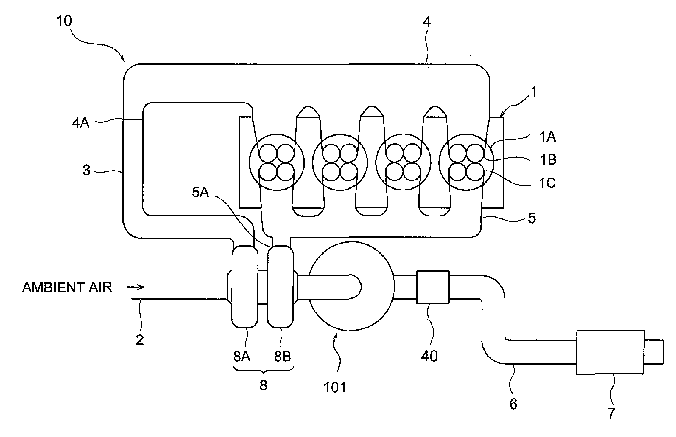
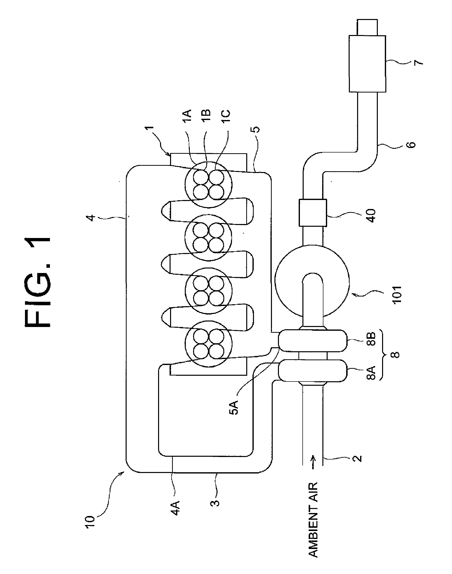
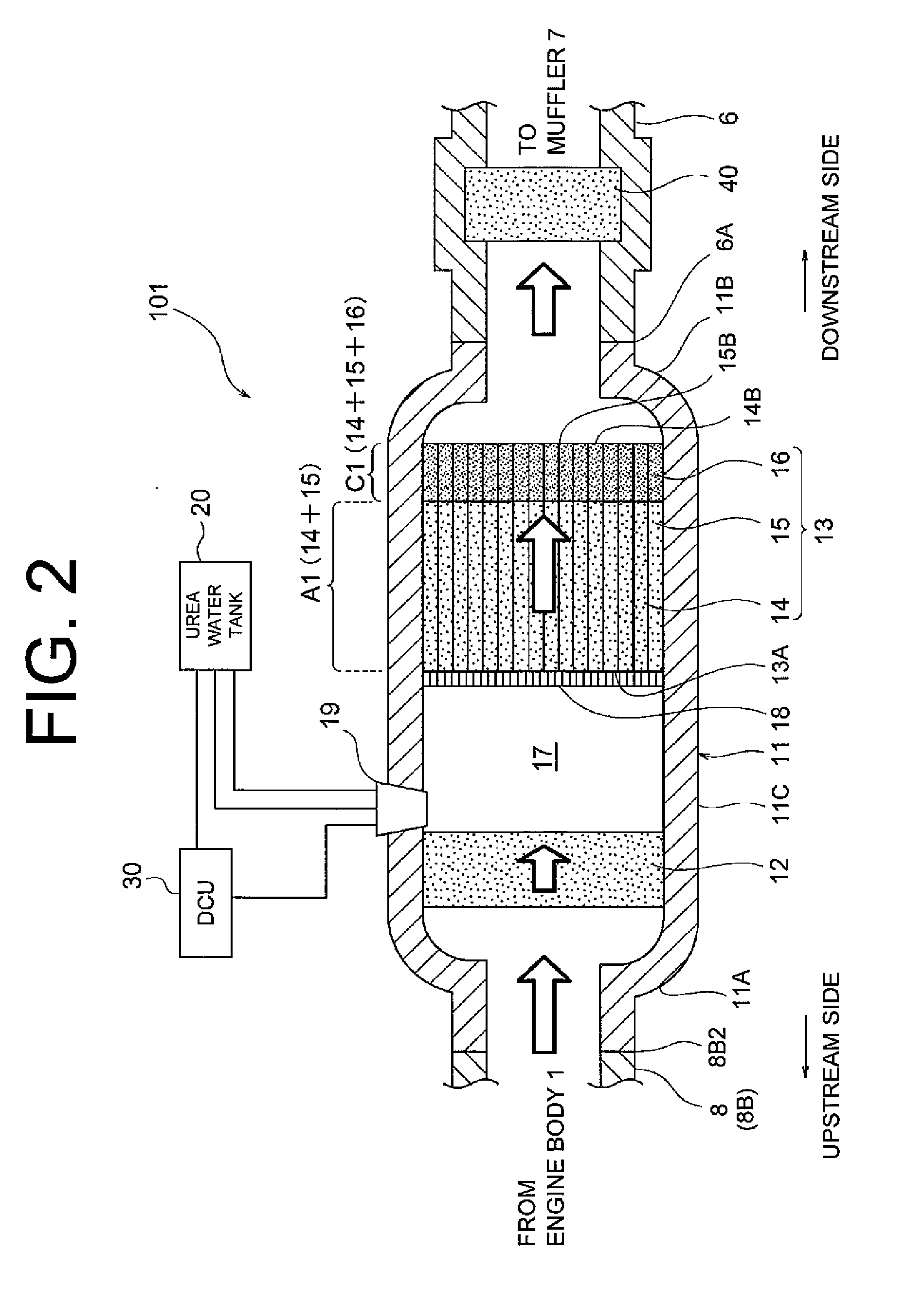
[0013]The following will describe a diesel engine and an exhaust gas purification apparatus 101 according to a first preferred embodiment of the present invention with reference to FIGS. 1 and 2. In the first preferred embodiment, the following will describe a case where the exhaust gas purification apparatus 101 is used in a diesel engine mounted on a vehicle.

[0014]Referring to FIG. 1, the diesel engine has an engine assembly 10 including an engine body 1, an intake pipe 3, an intake manifold 4, an exhaust manifold 5 and a turbocharger 8. The engine body 1 has a plurality of cylinders 1A each having a intake port 1B and an exhaust port 1C. The intake manifold 4 has an inlet 4A formed at one end thereof and is connected at the other end thereof to intake ports 1B of the respective cylinders 1A for delivering intake air to the cylinders 1A. The turbocharger 8 includes a compressor housing 8A and a turbine housing 8B. The intake pipe 3 is connected at one end thereof to the inlet 4A o...


PUM

PropertyMeasurementUnit
Temperatureaaaaaaaaaa

Abstract

An exhaust gas purification apparatus includes an exhaust gas passage, a first oxidation catalyst, a selective catalytic reduction catalyst, an oxidation-reduction catalyst and a urea water supply device. Exhaust gas is flowed through the first oxidation catalyst. The first oxidation catalyst is disposed in the exhaust gas passage. The selective catalytic reduction catalyst is disposed downstream of the first oxidation catalyst. The oxidation-reduction catalyst is disposed downstream of the selective catalytic reduction catalyst. The oxidation-reduction catalyst has reducing property and oxidizing property which are influenced by temperature, wherein the oxidizing property of the oxidation-reduction catalyst is greater than the reducing property of the oxidation-reduction catalyst under a temperature that is higher than a temperature under which the reducing property of the oxidation-reduction catalyst is greater than the oxidizing property of the oxidation-reduction catalyst. The urea water supply device supplies urea water upstream of the selective catalytic reduction catalyst.

Description

BACKGROUND OF THE INVENTION[0001]The present invention relates to an exhaust gas purification apparatus, and more particularly to an exhaust gas purification apparatus using a urea SCR (selective catalytic reduction) catalyst for reducing nitrogen oxides (NOX) contained in exhaust gas discharged from a diesel engine.[0002]A urea SCR system has been developed for reducing NOX contained in exhaust gas discharged from a diesel engine, which uses a SCR catalyst for reducing NOX by reaction thereof with ammonia (NH3) produced by hydrolyzing urea water thereby to form nitrogen (N2) and water (H2O).[0003]In the urea SCR system, the SCR catalyst is disposed in an exhaust gas passage provided between an engine and a muffler. In the exhaust gas passage, an oxidation catalyst and an injection valve are disposed upstream of the SCR catalyst, or on the side of the engine relative to the SCR catalyst. The oxidation catalyst is used for oxidizing hydrocarbons (HC) and carbon monoxide (CO) containe...

Claims


Application Information

Patent Timeline
IPC IPC(8): F01N3/10B01D50/00
CPCF01N3/035F01N3/106F01N3/108F01N13/0097F01N2240/20F01N2610/02Y02T10/24F01N3/2066Y02T10/12
Inventor KATO, YOSHIFUMI
Owner TOYOTA IND CORP
Learn More