

Reducing particle implantation
a particle beam and particle technology, applied in material analysis using wave/particle radiation, instruments, nuclear engineering, etc., can solve the problems of particle implantation in the sample, and achieve the effects of reducing particle implantation, reducing particle implantation, and eliminating induced variations in the sample surfa
- Summary
- Abstract
- Description
- Claims
- Application Information
AI Technical Summary
Benefits of technology
Problems solved by technology
Method used
Image

Examples
Embodiment Construction
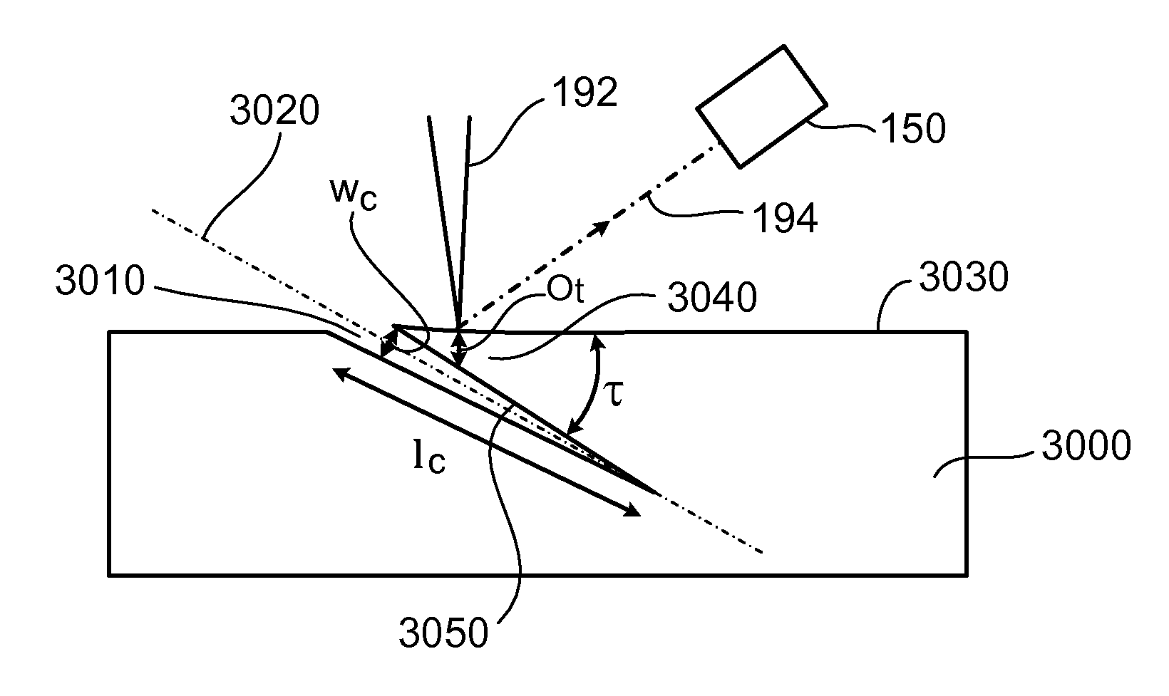
Exposure of certain materials to particle beams can lead to particle implantation within the materials. In this disclosure, the discussion will focus on particle beams that include helium (e.g., helium ion beams). However, the systems and methods disclosed herein can be used for a wide variety of particle beams, including neutral atom particle beams, and ion beams that include one of more of gallium ions, helium ions, neon ions, argon ions, krypton ions, xenon ions, and other types of ions. In general, the threshold particle dose at which implantation begins to occur depends upon a number of factors, including the material, the nature of the incident particles (e.g., helium ions, and / or other noble gas ions), the incident particle energies, and the incident particle currents.
For some samples, exposure to a helium ion beam can lead to implantation of helium. At sufficiently high doses of helium ions, the implanted helium can form bubble-like cavities beneath the surface of the sample...
PUM
| Property | Measurement | Unit |
|---|---|---|
| angle | aaaaa | aaaaa |
| width | aaaaa | aaaaa |
| width | aaaaa | aaaaa |
Abstract
Description
Claims
Application Information