Pattern transfer apparatus and pattern forming method

a technology of pattern forming and transfer apparatus, which is applied in the direction of photomechanical apparatus, applications, instruments, etc., can solve the problems of method not being used, preventing non-uniform film thickness, and increasing costs

Inactive Publication Date: 2011-03-03
FUJIFILM CORP
View PDF25 Cites 55 Cited by
  • Summary
  • Abstract
  • Description
  • Claims
  • Application Information

AI Technical Summary

Benefits of technology

[0034]As described above, according to the present invention, when depositing liquid of an imprint material onto a substrate by an inkjet method, even if there are

Problems solved by technology

However, in the related art described above, when applying the liquid onto the substrate, there are problems of the following kinds in preventing non-uniformity in the film thickness and achieving uniform film thickness.
For example, in the method described in Japanese Patent Application Publication No. 2007-313439, there are problems in that although uniform film thickness is achieved, costs increase due to the inclusion of additional steps, such as spin coating, and furthermore the method cannot be used when the liquid should be partially applied, to a portion to be imprinted, because the liquid is made to spread over the whole of the substrate surface ultimately by spin

Method used


Image

  • Pattern transfer apparatus and pattern forming method
  • Pattern transfer apparatus and pattern forming method
  • Pattern transfer apparatus and pattern forming method

Examples


Embodiment Construction

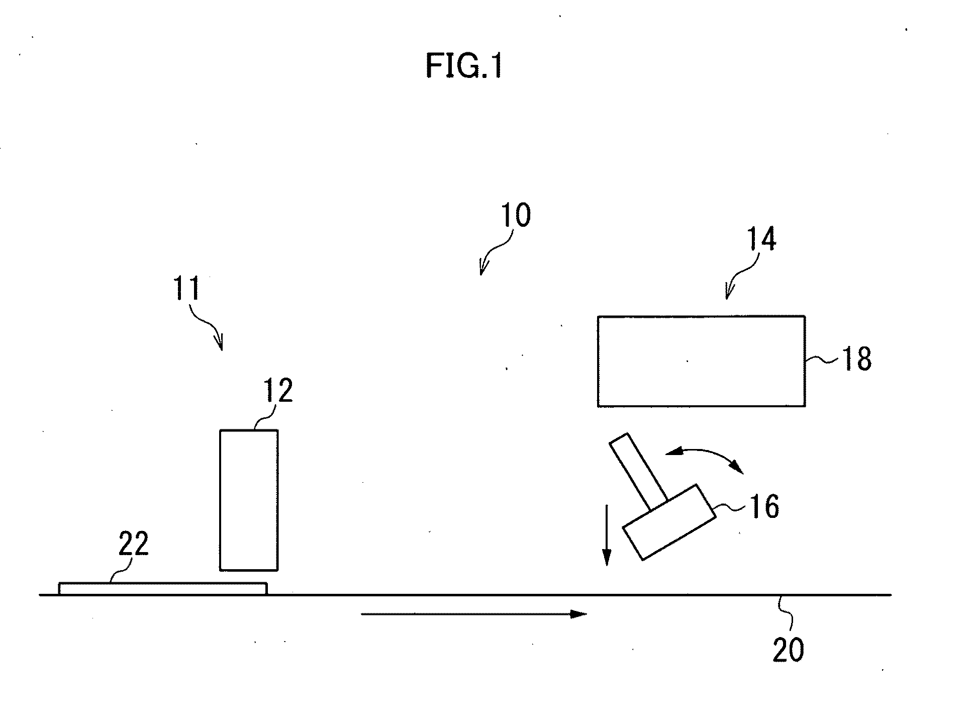
[0058]FIG. 1 is a general schematic drawing of a pattern transfer apparatus according to an embodiment of the present invention.

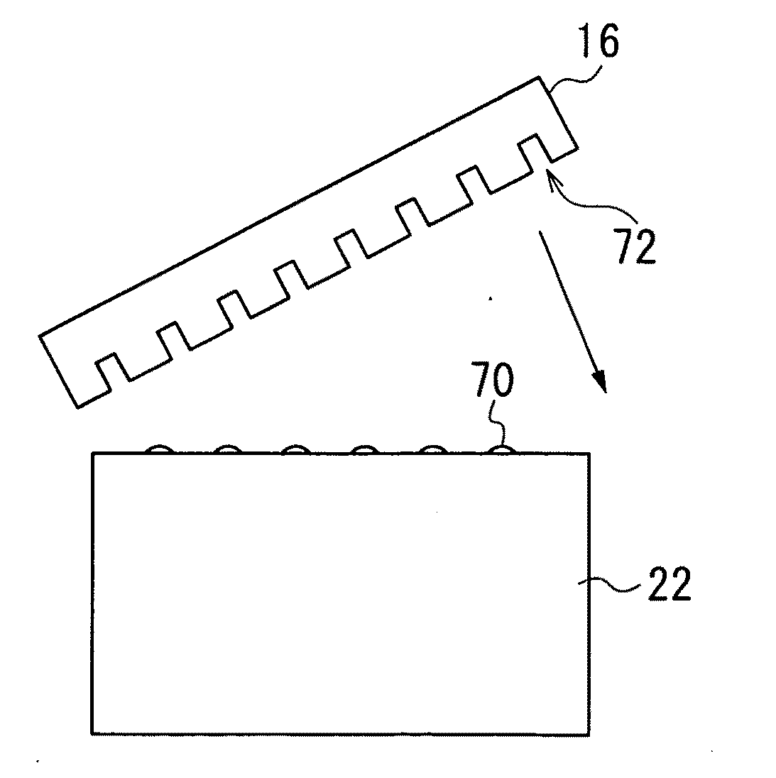
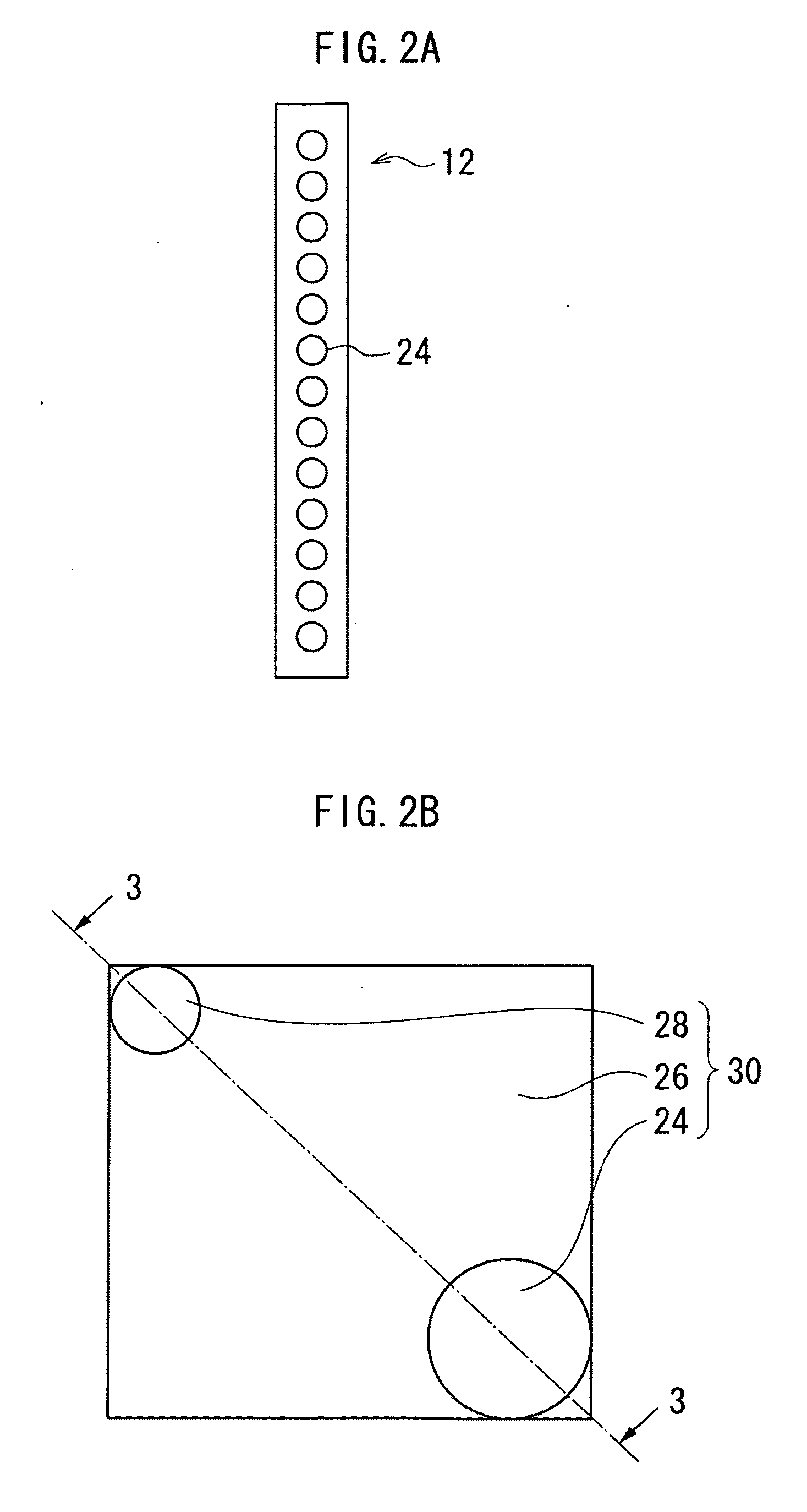
[0059]As shown in FIG. 1, the pattern transfer apparatus 10 in the present embodiment includes an inkjet liquid deposition unit 11 and a pattern forming unit 14. The inkjet liquid deposition unit 11 has an inkjet head (hereinafter referred to as a “recording head”) 12. The pattern forming unit 14 includes a mold (stamp) 16 having a surface in which a topographic pattern is formed, and an ultraviolet (UV) light irradiation device 18.

[0060]The recording head 12 deposits liquid of an imprint material on the surface of a substrate 22 by ejecting and depositing droplets of the liquid imprint material onto the surface of the substrate 22 which is conveyed on a conveyance device 20.

[0061]The substrate 22 on which the droplets of the liquid imprint material have been deposited is conveyed by the conveyance device 20 to the pattern forming unit 14, and a pattern is ...


PUM


Abstract

The pattern transfer apparatus includes: a liquid ejection device having liquid ejection ports through which droplets of liquid are ejected and deposited onto a substrate surface while the liquid ejection device relatively moves to scan the substrate surface in a relative scanning direction; and a stamp having a stamp surface on which a pattern is formed, the stamp surface being applied to the droplets of the liquid on the substrate surface in a stamp application direction while the stamp is relatively moved with respect to the substrate, wherein when defining, on the substrate surface, strips which are straight and parallel to the stamp application direction and have widths substantially equal to diameters of the droplets deposited on the substrate surface, at least one of the strips includes the droplets which are ejected respectively from at least different two of the liquid ejection ports of the liquid ejection device.

Description

CROSS-REFERENCE TO RELATED APPLICATIONS[0001]The present application claims priority from Japanese Patent Application No. 2009-200522, filed Aug. 31, 2009, the contents of which are herein incorporated by reference in their entirety.BACKGROUND OF THE INVENTION[0002]1. Field of the Invention[0003]The present invention relates to a pattern transfer apparatus and a pattern forming method, and more particularly to a pattern transfer apparatus and a pattern forming method whereby a pattern is transferred onto a substrate by applying a mold on which the pattern has been formed onto a surface of the substrate on which liquid has been applied, curing the liquid, and then removing the mold.[0004]2. Description of the Related Art[0005]Photo nanoimprint lithography is known as a method of forming patterns in a manufacturing process which requires high-resolution processing, such as semiconductor device fabrication. In the photo nanoimprint lithography, a mold having topological patterns is pre...

Claims


Application Information

Patent Timeline
IPC IPC(8): B29C59/02
CPCB82Y10/00G03F7/0002B82Y40/00
Inventor MATAKI, HIROSHI
Owner FUJIFILM CORP
Why Eureka
Try Eureka