Movable sweat hearth for metal melting furnace

Active Publication Date: 2011-03-03
NOVELIS INC
View PDF8 Cites 1 Cited by
  • Summary
  • Abstract
  • Description
  • Claims
  • Application Information

AI Technical Summary

Benefits of technology

[0018]In all exemplary embodiments, the slope of the floor (when the sweat hearth is in the operating position) is made s

Problems solved by technology

Scrap materials made of aluminum or other metals (e.g. copper) can be re-melted for re-use, but they may be contaminated and may require pre-treatment to remove or reduce such contaminants before they can be added directly to a melting furnace.
However, metal foil is so thin that it would be converted almost entirely to oxide in such furnaces and is thus re-melted by other means.
Uncoated (clean) scrap may be added directly to the main chamber of the furnace, but it is often wet or contaminated with water (e.g. water contained within internal shrinkage cavities formed in large castings).
If water-contaminated scrap is added directly to the furnace, there is a risk of explosion, so the contaminating water has to be dr

Method used


Image

  • Movable sweat hearth for metal melting furnace
  • Movable sweat hearth for metal melting furnace
  • Movable sweat hearth for metal melting furnace

Examples


Example

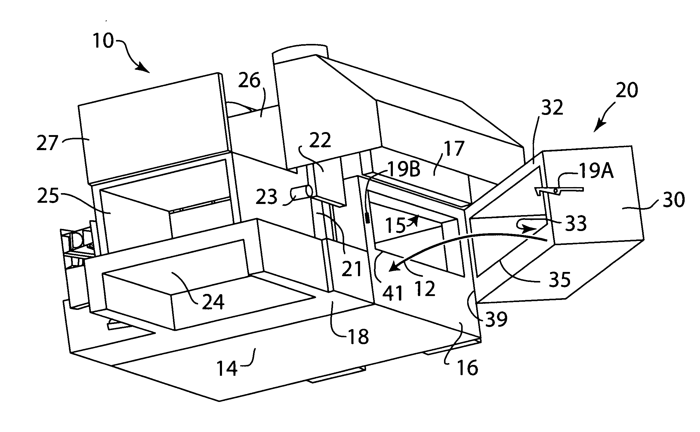
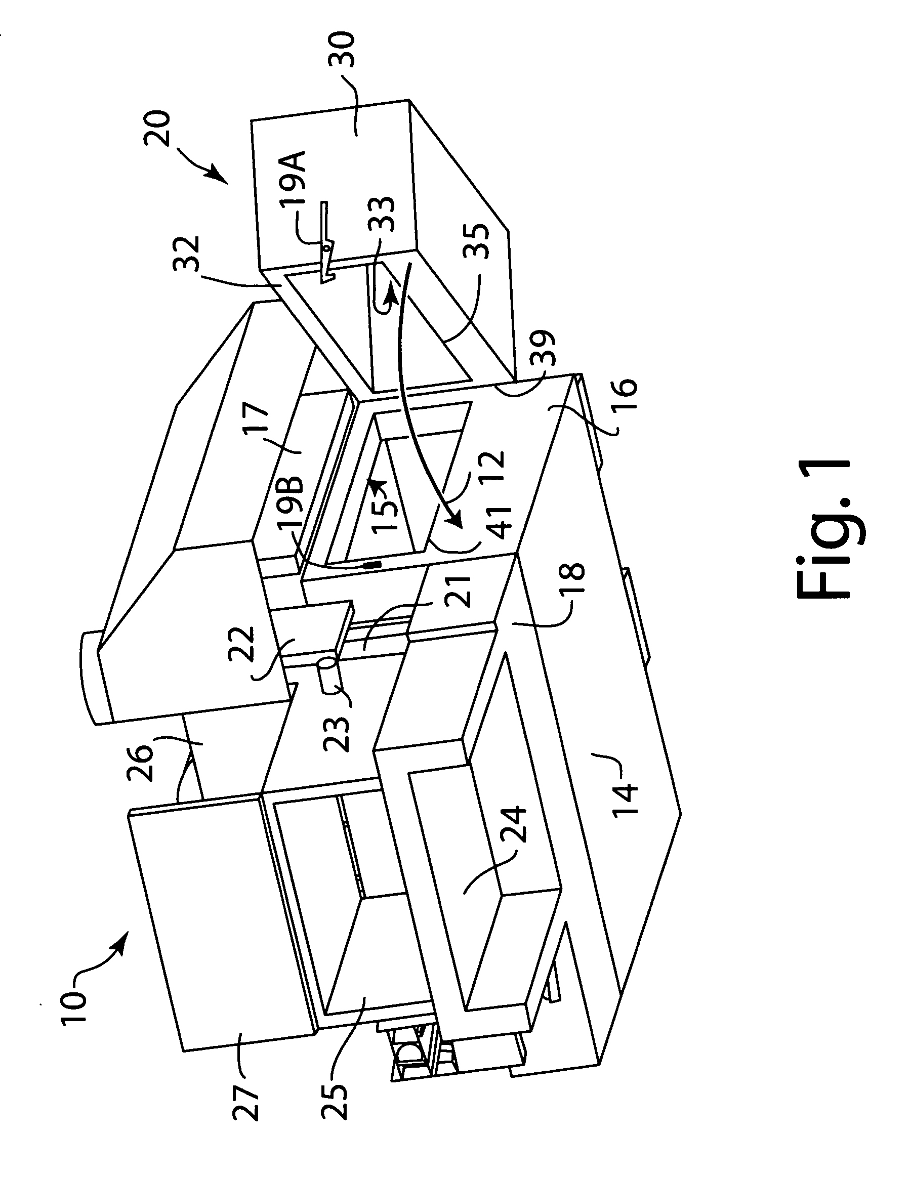
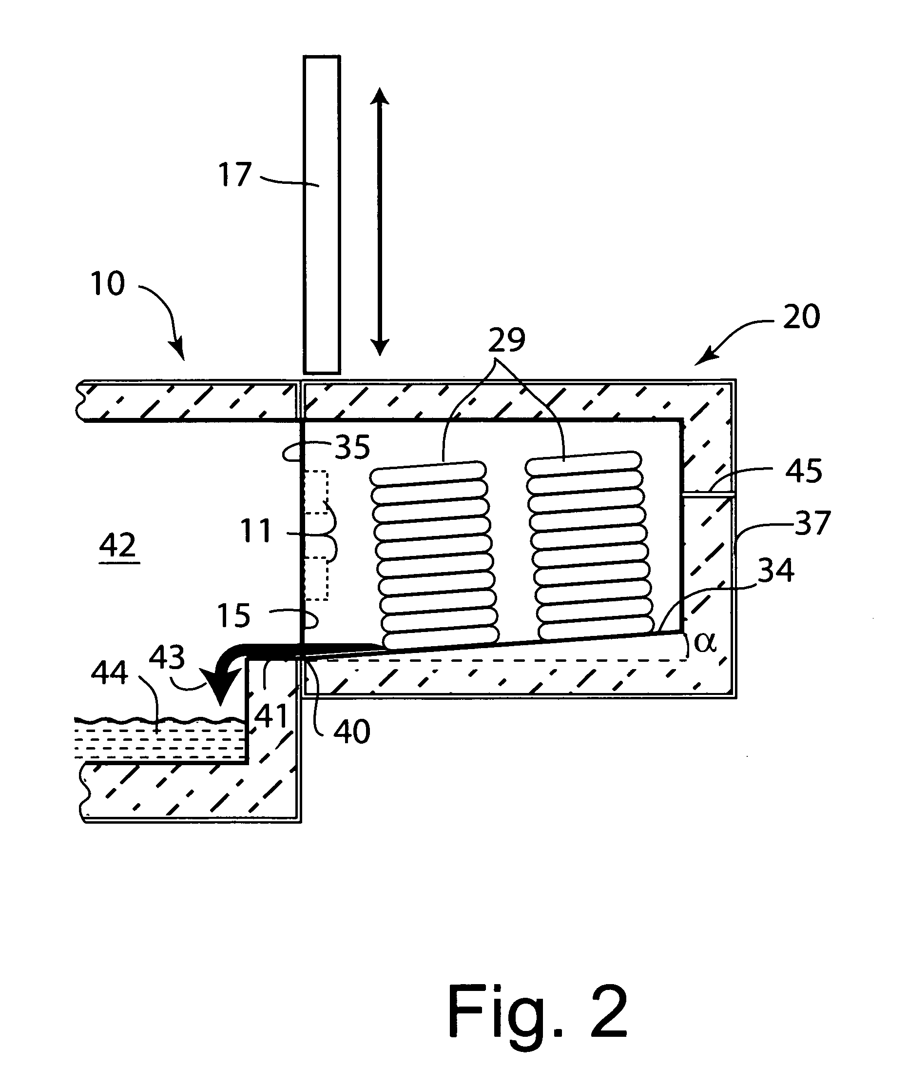
[0028]A first exemplary embodiment of this invention is shown in FIGS. 1 and 2 of the accompanying drawings. The apparatus illustrated in FIG. 1 is a combination of a reverberatory furnace 10 and a movable sweat hearth 20. FIG. 2 shows the sweat hearth 20 and just an adjacent part of the furnace.

[0029]The furnace 10 has a main chamber 14 provided with a main furnace entrance 15, normally used for metal-loading, in a generally planar vertical furnace front wall 16, which entrance can be used for loading scrap or new metal and can be opened or closed by a vertically movable furnace door 17 (shown in the open position in FIG. 1). The furnace door, when closed, prevents the loss of undue heat from the furnace through the metal-loading entrance 15 in the form of hot air and radiant heat. The furnace 10 has a side well 18 that communicates with the main chamber 14 via openings (not shown) below the normal surface level of molten aluminum alloy within the main chamber. The side well 18 has...


PUM

PropertyMeasurementUnit
Angleaaaaaaaaaa
Angleaaaaaaaaaa
Angleaaaaaaaaaa

Abstract

Exemplary embodiments provide a movable sweat hearth for use with a metal melting furnace having a wall provided with a metal-loading entrance. The sweat hearth includes a hearth body movable relative to the furnace into and out of contact with the wall of the furnace at the entrance. The body has exterior walls enclosing a hollow interior except at a furnace-engagable side wall of the hearth body provided with an opening communicating with the interior. The interior has a floor adapted to support a charge of scrap metal, and the opening is positioned relative to the floor to allow molten metal to drain from the interior through the opening. The floor is arranged at an angle to horizontal to slope in a downward direction towards the opening when the container is moved into sealing engagement with the wall of the furnace with the opening aligned with the furnace entrance. Other exemplary embodiments relate to a combination of a movable sweat hearth as described above and a metal melting furnace having a front wall provided with a furnace entrance.

Description

CROSS-REFERENCE TO RELATED APPLICATION[0001]This application claims the priority right of prior co-pending U.S. provisional patent application Ser. No. 61 / 275,388 filed Aug. 28, 2009 by applicants herein. The entire contents of application Ser. No. 61 / 275,388 are specifically incorporated herein by this reference.BACKGROUND OF THE INVENTION[0002](1) Field of the Invention[0003]This invention relates to apparatus for melting metal scrap material, particularly aluminum scrap material. More particularly, the invention relates to apparatus for pre-treating metal scrap material and for transferring the pre-treated scrap material to a melting furnace, e.g. a reverberatory furnace or direct-charged convective furnace.[0004](2) Description of the Related Art[0005]Scrap materials made of aluminum or other metals (e.g. copper) can be re-melted for re-use, but they may be contaminated and may require pre-treatment to remove or reduce such contaminants before they can be added directly to a mel...

Claims


Application Information

Patent Timeline
IPC IPC(8): F27B3/00F27D5/00
CPCF27B3/18F27D3/0031F27D3/003Y02P10/20F27D3/12F27D13/00
Inventor RAUCH, EDWIN L.
Owner NOVELIS INC
Why Eureka
Try Eureka