Integrated Voltage Regulator with Embedded Passive Device(s)

a voltage regulator and passive device technology, applied in the field of integrated circuits, can solve the problems of voltage drop between the voltage regulator and the die that the voltage regulator, and the conventional voltage regulators have slow response times,

Inactive Publication Date: 2011-03-03
QUALCOMM INC
View PDF12 Cites 70 Cited by
  • Summary
  • Abstract
  • Description
  • Claims
  • Application Information

AI Technical Summary

Problems solved by technology

Only tenths of a volt lower may create erratic results in the die; only tenths of a volt higher may damage the die.
Placing the voltage regulator on the PCB separate from the die results in a voltage drop between the voltage regulator and the die that the voltage regulator supplies.
Further, conventional voltage regulators have slow response times due to the distance between the voltage regulator and the die.
Passive devices consume die area, which increases manufacturing cost.
In addition to consuming large areas on a die, conventional on-die inductors have a low quality factor.
A quality factor for passive components embedded in a die is low because the passive components are manufactured thin to fit in the die.
As the amount of conducting material shrinks, conductive or magnetic losses increase and degrade the quality factor.

Method used


Image

  • Integrated Voltage Regulator with Embedded Passive Device(s)
  • Integrated Voltage Regulator with Embedded Passive Device(s)
  • Integrated Voltage Regulator with Embedded Passive Device(s)

Examples


first embodiment

[0035]FIG. 4 is a cross-sectional view illustrating an exemplary voltage regulator on a die according to a An IC product 400 includes a packaging substrate 420 coupled to a PCB 410 through a packaging connection 422 such as bumps or pillars. The packaging substrate 420 includes embedded passive components that may store energy in magnetic or electric form. For example, an embedded inductor 450 and an embedded capacitor 460 are at least partially embedded in the packaging substrate 420. The embedded inductor 450 and / or the embedded capacitor 460 may use embedded die substrate (EDS) technology. In one embodiment, the embedded capacitor 460 may have capacitance values in the hundreds of nanoFarads and provide decoupling capacitance to a die 430. The die 430 is coupled to the packaging substrate 420 through an interconnect structure 432 such as bumps or pillars.

[0036]Manufacturing the embedded inductor 450 and the embedded capacitor 460 in the packaging substrate 420 may use a laminati...

second embodiment

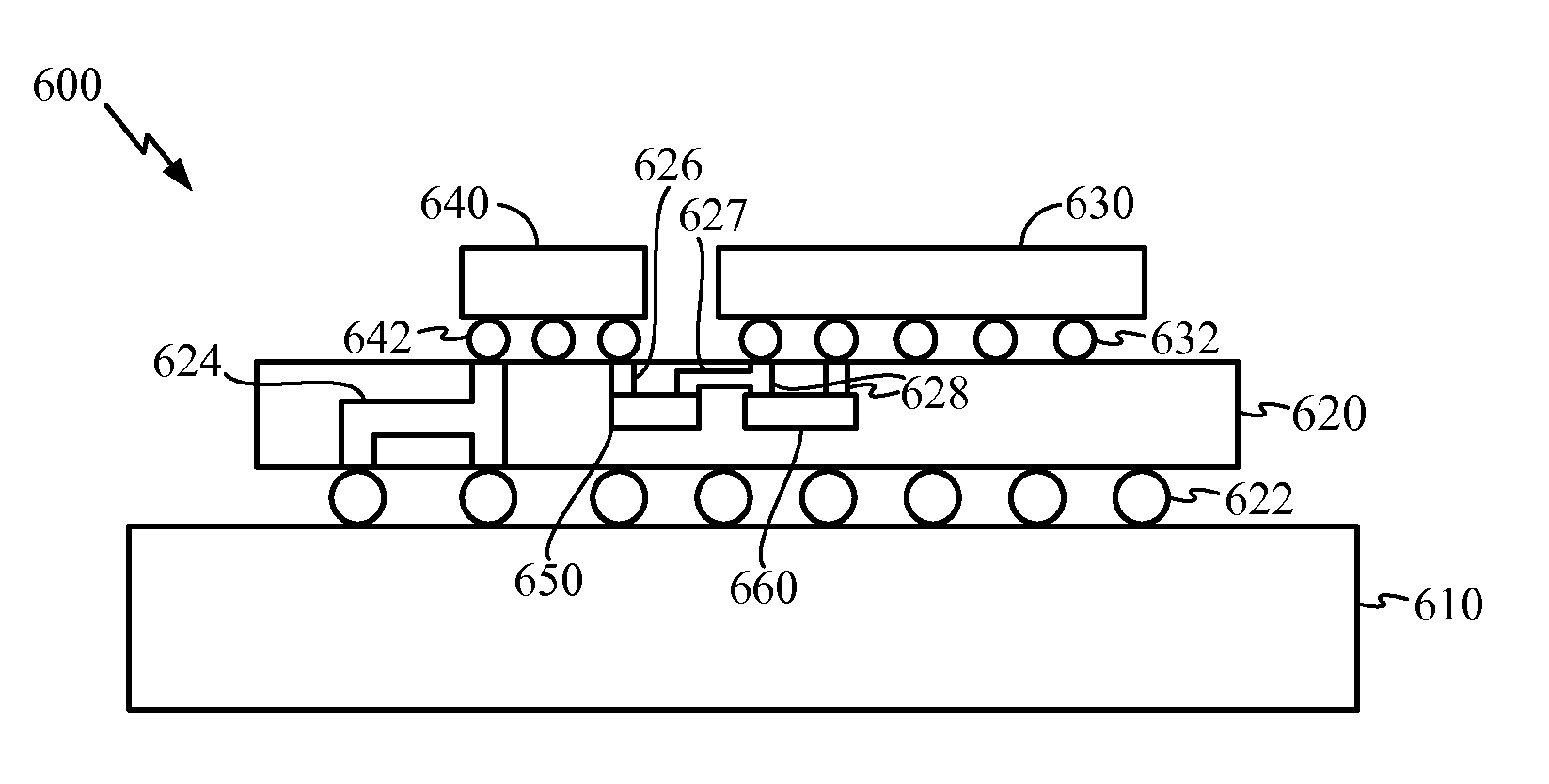
[0039]In an alternative configuration, some of the embedded passive components may be replaced with vias in the packaging substrates. FIG. 5 is a cross-sectional view illustrating an exemplary voltage regulator on a die with an embedded parasitic inductance according to a

[0040]The packaging substrate 420 includes vias 526 having a parasitic inductance used by the active portion of the voltage regulator 440 as inductors for supplying voltage to the die 430. The vias 526 may be through vias, which extend the entire height of the packaging substrate 420. The through vias 526 may be coupled through the packaging connection 422 to through vias 516 in the PCB 410 if a larger inductance is desired than obtained with the through vias 526 alone. The use of parasitic inductance in through vias within the packaging substrate as a passive component simplifies semiconductor manufacturing by reducing a number of processes to embed inductors in the packaging substrate.

[0041]According to a third em...

fifth embodiment

[0046] inductance is provided by wirebonds. FIG. 7B is a cross-sectional view illustrating an exemplary voltage regulator with a wirebond inductance. A wirebond 750 couples the active portion of the voltage regulator 640 to one of the vias 716. The wirebond 750, the vias 716 and the conducting layer 730 provide inductance to the active portion of the voltage regulator 640.

[0047]Embedded passives in which through vias provide inductance for a voltage regulator will now be described in further detail. FIGS. 8A-C are block diagrams illustrating paths through a packaging substrate and PCB that may provide inductance. FIG. 8A is a block diagram illustrating a path 800 through a packaging substrate and PCB according to one embodiment. A top conductive layer 802 and a bottom conductive layer 810 of a packaging substrate are shown. Inner layers 804, 806 of the packaging substrate are also shown. A through via 805, couples the top conductive layer 802 and the bottom conductive layer 810. A p...


PUM

PropertyMeasurementUnit
sizeaaaaaaaaaa
wall voltageaaaaaaaaaa

Abstract

A semiconductor packaging system has a packaging substrate into which inductors and / or capacitors are partially or completely embedded. An active portion of a voltage regulator is mounted on the packaging substrate and supplies regulated voltage to a die also mounted on the packaging substrate. Alternatively, the active portion of the voltage regulator is integrated into the die the voltage regulator supplies voltage to. The voltage regulator cooperates with the inductors and / or capacitors to supply voltage to the die. The inductors may be through vias in the packaging substrate. For additional inductance, through vias in a printed circuit board on which the packaging substrate is mounted may couple to the through vias in the packaging substrate.

Description

TECHNICAL FIELD[0001]The present disclosure generally relates to integrated circuits (ICs). More specifically, the present disclosure relates to manufacturing integrated circuits.BACKGROUND[0002]Integrated circuits (ICs) are fabricated on wafers. Commonly, these wafers are semiconductor materials, such as silicon, and singulated to form individual dies. Through efforts of research and development, the size of the transistors making up the ICs has decreased to 45 nm and will soon decrease to 32 nm. As transistor size decreases, the supply voltage to the transistors decreases. The supply voltage is conventionally smaller than wall voltages available in most countries or battery voltages used in portable devices. For example, an IC may operate at 1.25 Volts whereas the wall voltage is 120V or 240V. In a portable device, such as cellular phone, the battery voltage may range from 6V at full charge to 3V at near empty charge.[0003]A semiconductor die may be coupled to a voltage regulator ...

Claims


Application Information

Patent Timeline
Patent Type & Authority Applications(United States)
IPC IPC(8): H01L25/00
CPCH01L2924/15192H01L2224/16225H01L25/16H05K1/141H01L2924/15174H05K1/0262H02M3/00Y10T29/4913H01L2924/15311H01L23/645H05K1/185H01L25/0652H01L23/642H02M3/003H01L2224/16235
Inventor PAN, YUANCHENG CHRISTOPHERCHUA-EOAN, LEW G.ZHU, ZHIZHANG, JUNMOU
Owner QUALCOMM INC
Why Eureka
Try Eureka