System and method for correcting global navigation satellite system carrier phase measurements in receivers having controlled reception pattern antennas

Active Publication Date: 2011-03-03
RAYTHEON CO
View PDF29 Cites 33 Cited by
  • Summary
  • Abstract
  • Description
  • Claims
  • Application Information

AI Technical Summary

Benefits of technology

[0018]Therefore, with the conversion from the FRPA based systems to the CRPA systems for GNSS applications, there is a need to better compensate for the effects of antenna element errors on carrier phase measurement errors.
[0019]Embodiments of the present invention provide a system and method for correcting errors in GNSS carrier phase measurements that use CRPA receiver systems. The method is implemented as a correction to

Problems solved by technology

This clock error is common to all measurements since the atomic satellite clocks are all synchronized, and results in a common range error.
Other effects that give rise to range errors include atmospheric and receiver antenna hardware.
Nonetheless, other effects that contribute to range measurement errors still remain.
Atmospheric (i.e., ionospheric and tropospheric) conditions are usually the next most significant source of error.
There are still other effects, most notably receiver antenna hardware, which cannot be compensated through any of the above techniques.
To the extent that such effects are not common between different satellites (common errors disappear as part of the clock bias correction calculated when determining location), they can affect the accuracy of the resulting positional calculation.
Multiple element receiver antennas add complexity to the mitigation of these non-common errors, because the different elements receive and process the satellite signals with different hardware.
Each hardware path contributes a different delay to the overall measured time of reception.
Because the satellite signals are relatively weak, it is fairly straightforward to intentionally jam such signals, either by increasing the noise floor by transmitting a broadband noise jammer or by attempting to exceed the dynamic range of the receiver hardware with powerful narrowband signals.
This is unacceptable for military applications, so they rely on encrypted signals to thwart any spoofed transmissions, but are still susceptible to intentional interference on the same frequencies.
Intentional interference is usually significantly stronger than actual satellite transmissions.
The problem is that the phase center of reception of such waves can be difficult to determine for multiple element antennas tracking satellites from different angles.
Without compensation, this effect contributes error when performing GNSS carrier phase measurements.
However, for the complex case of a GNSS receiver employing a CRPA and dynamic beam steering, the multiplicity of combinations of antenna element outputs makes compensation more difficult, as the simple subtraction used for FRPA compensation does not work with a CRPA.
Compensation of carrier phase measurements for such errors is a problem not addressed in previous GNSS CRPA beam steering sensors.

Method used


Image

  • System and method for correcting global navigation satellite system carrier phase measurements in receivers having controlled reception pattern antennas
  • System and method for correcting global navigation satellite system carrier phase measurements in receivers having controlled reception pattern antennas
  • System and method for correcting global navigation satellite system carrier phase measurements in receivers having controlled reception pattern antennas

Examples


Embodiment Construction

[0031]The illustrative embodiments that follow are only exemplary applications of the present invention and not intended to limit the scope of the invention.

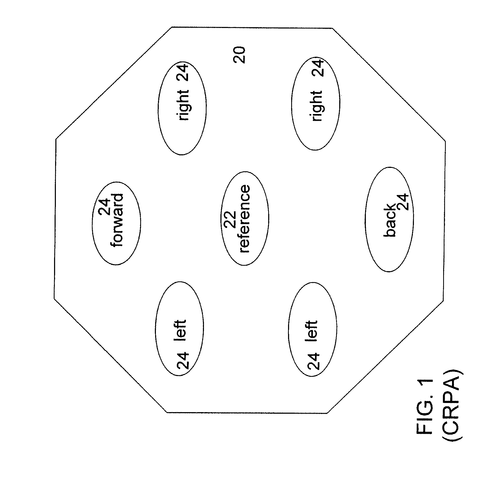
[0032]A preferred embodiment of the invention comprises a GNSS CRPA receiver system on a dynamic platform, such as an aircraft. FIG. 1 shows an exemplary CRPA 20 comprising seven antenna elements (channels). In FIG. 1, the seven elements are comprised of one reference element 22 and six auxiliary elements 24, where the reference element 22 is the principal element centered with respect to the seven elements while the six auxiliary elements 24 surround the reference element 22 in a symmetrical layout: one forward, one back, two on the left, and two on the right. Note that a CRPA may consist of other numbers of elements, and the elements may differ in relative orientation, which may be either symmetric or asymmetric.

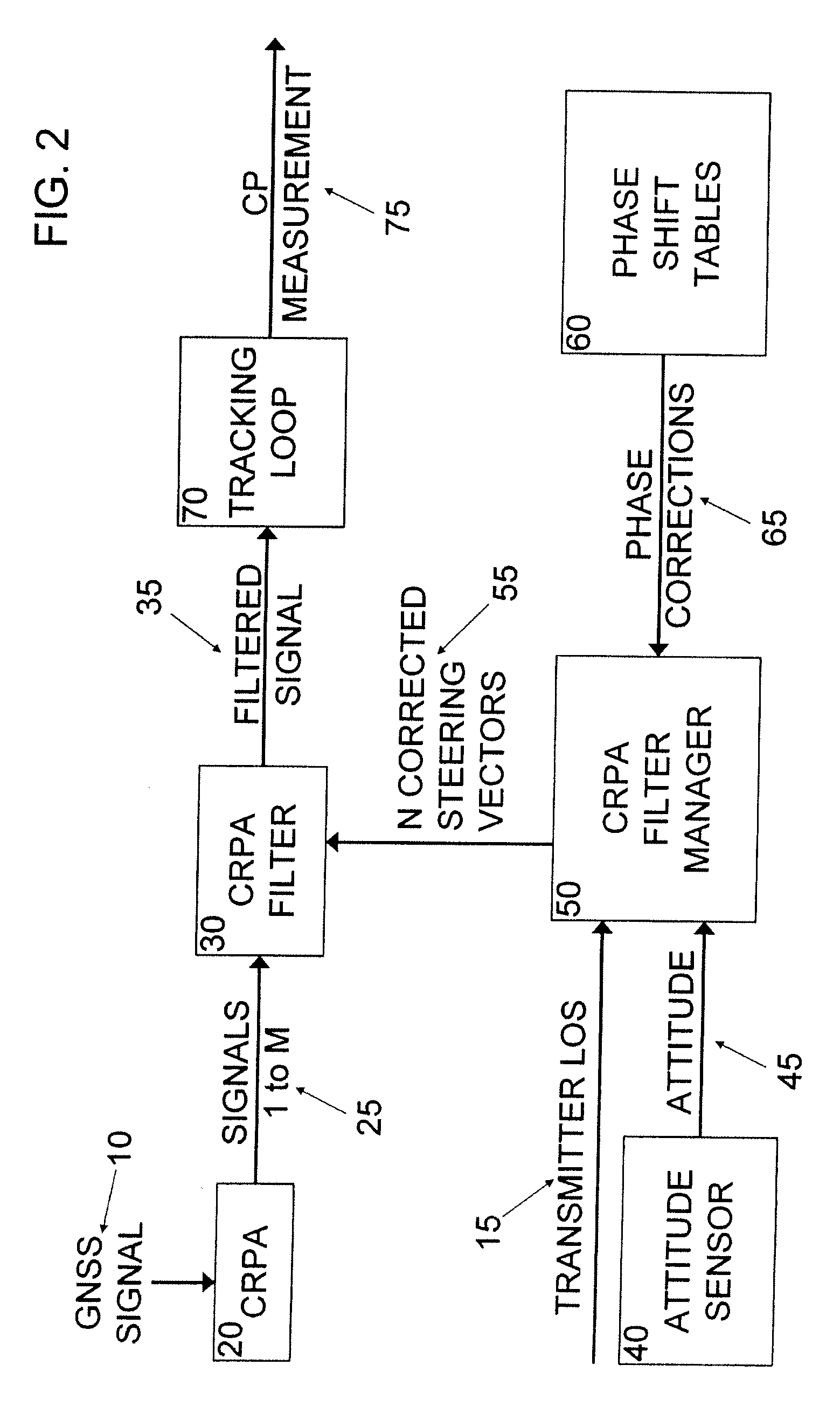
[0033]Referring now to FIG. 2, CRPA 20 receives a signal 10 from one or more radio navigation transmitters, such as ...


PUM


Abstract

This invention discloses a method for enhancing a Global Navigation Satellite System (GNSS), such as Global Positioning System (GPS), location calculation by supplying carrier phase corrections within a GNSS receiver used with a multiple element Controlled Reception Pattern Antenna (CRPA) receiver. GNSS carrier phase measurements should be compensated for receiver hardware and directionally dependent antenna errors to obtain desired accuracies for high precision GNSS positioning applications. One technique successfully employed in Fixed Reception Pattern Antenna (FRPA) GPS sensors applies a simple directionally dependent set of correction factors to the measurement outputs. For the complex case of a GNSS receiver employing a CRPA and dynamic beam steering, however, the multiplicity of combinations of antenna element outputs makes the FRPA compensation technique impractical. Compensation of carrier phase measurements is a problem not addressed in previous GPS CRPA beam steering sensors.

Description

CROSS-REFERENCE TO RELATED APPLICATION(S)[0001]This application is related to U.S. patent application entitled “SYSTEM AND METHOD FOR CORRECTING GLOBAL NAVIGATION SATELLITE SYSTEM PSEUDORANGE MEASUREMENTS IN RECEIVERS HAVING CONTROLLED RECEPTION PATTERN ANTENNAS,” filed <concurrently herewith>, the entire content of which is incorporated herein by reference.STATEMENT REGARDING FEDERALLY SPONSORED RESEARCH OR DEVELOPMENT[0002]This invention was made with government support under Contract No. N00019-02-C-3002 awarded by the Department of the Navy. The government has certain rights to this invention.BACKGROUND OF THE INVENTION[0003]1. Field of the Invention[0004]The present invention relates to the field of Global Navigation Satellite Systems (GNSS), such as the Global Positioning System (GPS), and, more particularly, to carrier phase measurements in such systems.[0005]2. Description of the Related Art[0006]Global Navigation Satellite Systems (GNSS) use a constellation of dispers...

Claims


Application Information

Patent Timeline
IPC IPC(8): H01Q3/00
CPCG01S19/29G01S19/23
Inventor MAENPA, JON E.HAUTZIK, ANDREW M.SAIN, PARTRICK M.
Owner RAYTHEON CO
Why Eureka
Try Eureka