
Planar Antenna Array and Article of Manufacture Using Same

a technology of antenna array and antenna array, which is applied in the direction of antenna details, antennas, basic electric elements, etc., can solve the problems of damage to basic cell structure and dna, and achieve the effects of reducing stress, reducing the harmful effects of low-intensity emf radiation on humans, and reducing the harmful effects of emf radiation

Active Publication Date: 2011-03-03
SVR INVENTIONS
View PDF5 Cites 6 Cited by
  • Summary
  • Abstract
  • Description
  • Claims
  • Application Information

AI Technical Summary

Benefits of technology

"The patent is about a new type of antenna that can reduce the harmful effects of low-intensity electromagnetic fields on humans. It also improves balance, flexibility, energy, strength, recovery, immunity, and relaxation, while reducing stress. The antenna is made up of close-packed elements that have a spiral shape. It can be used in various products like cell phones or clothing."

Problems solved by technology

High intensity EMF radiation damages basic cell structure and DNA.

Method used


Image

  • Planar Antenna Array and Article of Manufacture Using Same
  • Planar Antenna Array and Article of Manufacture Using Same
  • Planar Antenna Array and Article of Manufacture Using Same

Examples


Embodiment Construction

[0018]While the making and using of various embodiments of the present invention are discussed in detail below, it should be appreciated that the present invention provides many applicable inventive concepts which can be embodied in a wide variety of specific contexts. The specific embodiments discussed herein are merely illustrative of specific ways to make and use the invention, and do not delimit the scope of the present invention.

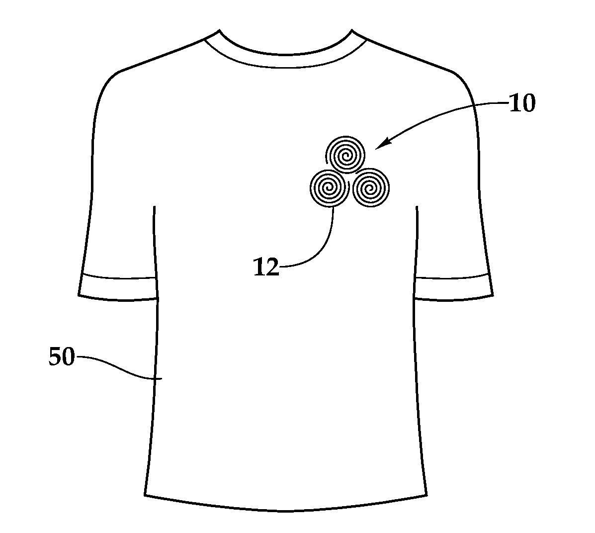
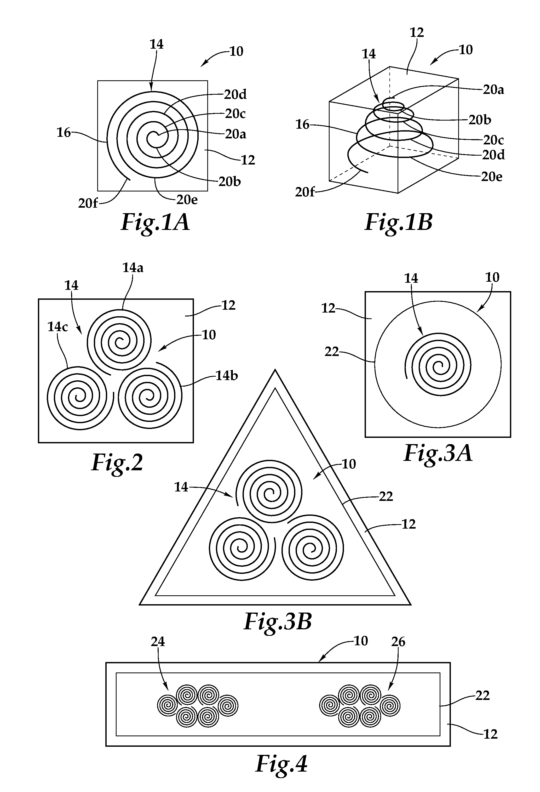
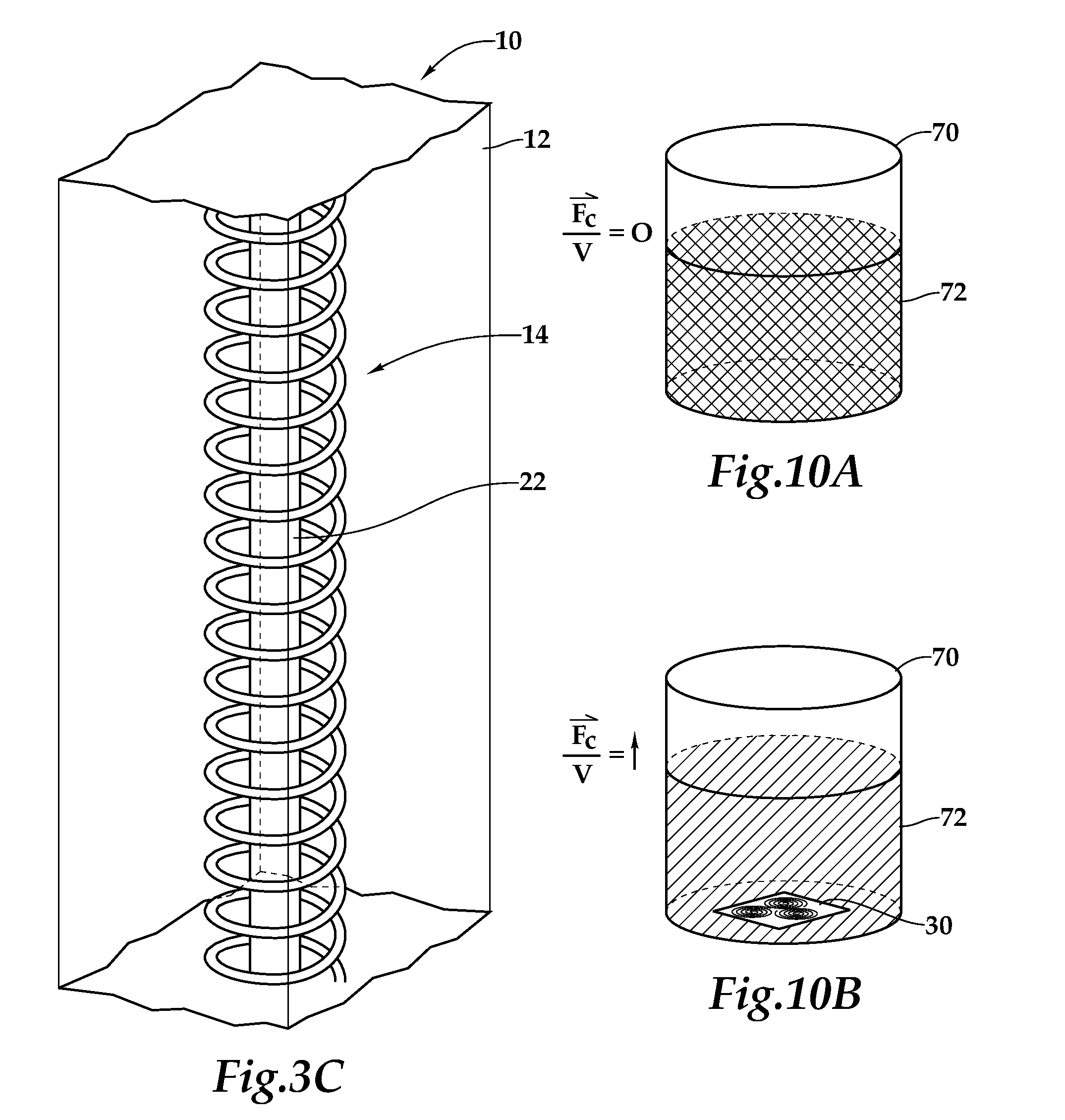
[0019]Referring initially to FIG. 1A, therein is depicted a planar antenna array that is schematically illustrated and generally designated 10. The planar antenna array 10 includes a substrate 12 having an antenna element 14 disposed thereon, which includes a substantially continuous photonic transducer 16 arranged as an outwardly expanding generally logarithmic spiral 18 or spiral lattice having six turns 20A, 20B, 20C, 20D, 20E, 20F. The photonic transducer 16 may be a clockwise or counterclockwise spiral and, as discussed below, have any type of phas...


PUM


Abstract

A planar antenna array and articles of manufacture using the same are disclosed. In one embodiment, close-packed antenna elements, disposed on a substrate, number N where N=3x and x is a positive integer. Each of the close-packed antenna elements includes a substantially continuous photonic transducer arranged as an outwardly expanding generally logarithmic spiral having six turns. Each of the outwardly expanding generally logarithmic spirals may be a golden spiral. As an article of manufacture, the planar antenna array may be incorporated into a chip, such as a cell phone, or an article of clothing, for example.

Description

TECHNICAL FIELD OF THE INVENTION[0001]This invention relates, in general, to antenna arrays of radiating and receiving elements and, in particular, to planar arrays of radiating and receiving elements including spiral lattices and articles of manufacture using the same.BACKGROUND OF THE INVENTION[0002]Without limiting the scope of the present invention, its background will be described with reference to electromagnetic field (EMF) radiation interacting with humans, as an example. The negative effects of high intensity EMF radiation on humans have been proved conclusively. High intensity EMF radiation damages basic cell structure and DNA. With respect to low intensity EMF radiation, it is now acknowledged that EMF radiation influences the environment. The degree to which short-term and long-term exposure to low intensity EMF radiation impacts humans is now an area of ongoing study and intense debate with credible evidence mounting that demonstrates the degree to which short-term and ...

Claims


Application Information

Patent Timeline
Patent Type & Authority Applications(United States)
IPC IPC(8): H01Q1/36H01Q1/12
CPCH01Q1/273H01Q21/067H01Q21/061H01Q1/36H01Q21/06H01Q7/00
Inventor REAVIS, KATHRYNSUDDATH, RALPHVANCE, DON
Owner SVR INVENTIONS
Learn More