Fluid machine

a technology of fluid machine and split-pipe, which is applied in the direction of positive displacement liquid engine, positive displacement pump components, piston pumps, etc., can solve the problems of affecting the service life of the coil, the efficiency of the linear motor with the split-pipe located in between, and the efficiency of the linear motor with the split-pipe located outsid

Inactive Publication Date: 2011-03-03
ANDREAS HOFER HOCHDRUCKTECHN +1
View PDF9 Cites 26 Cited by
  • Summary
  • Abstract
  • Description
  • Claims
  • Application Information

AI Technical Summary

Benefits of technology

[0010]The object of this invention is to provide the initially described fluid machine for compression or conveyance of fluids with a structure that is as simple a

Problems solved by technology

In this way, electrical losses as a result of eddy currents occur in the split pipe and the split pipe is heated so that the efficiency of the linear motor with the split-pipe located in between is less than the efficiency of a linear motor with a split pipe which lies outside.
This disadv

Method used


Image

  • Fluid machine
  • Fluid machine
  • Fluid machine

Examples


Embodiment Construction

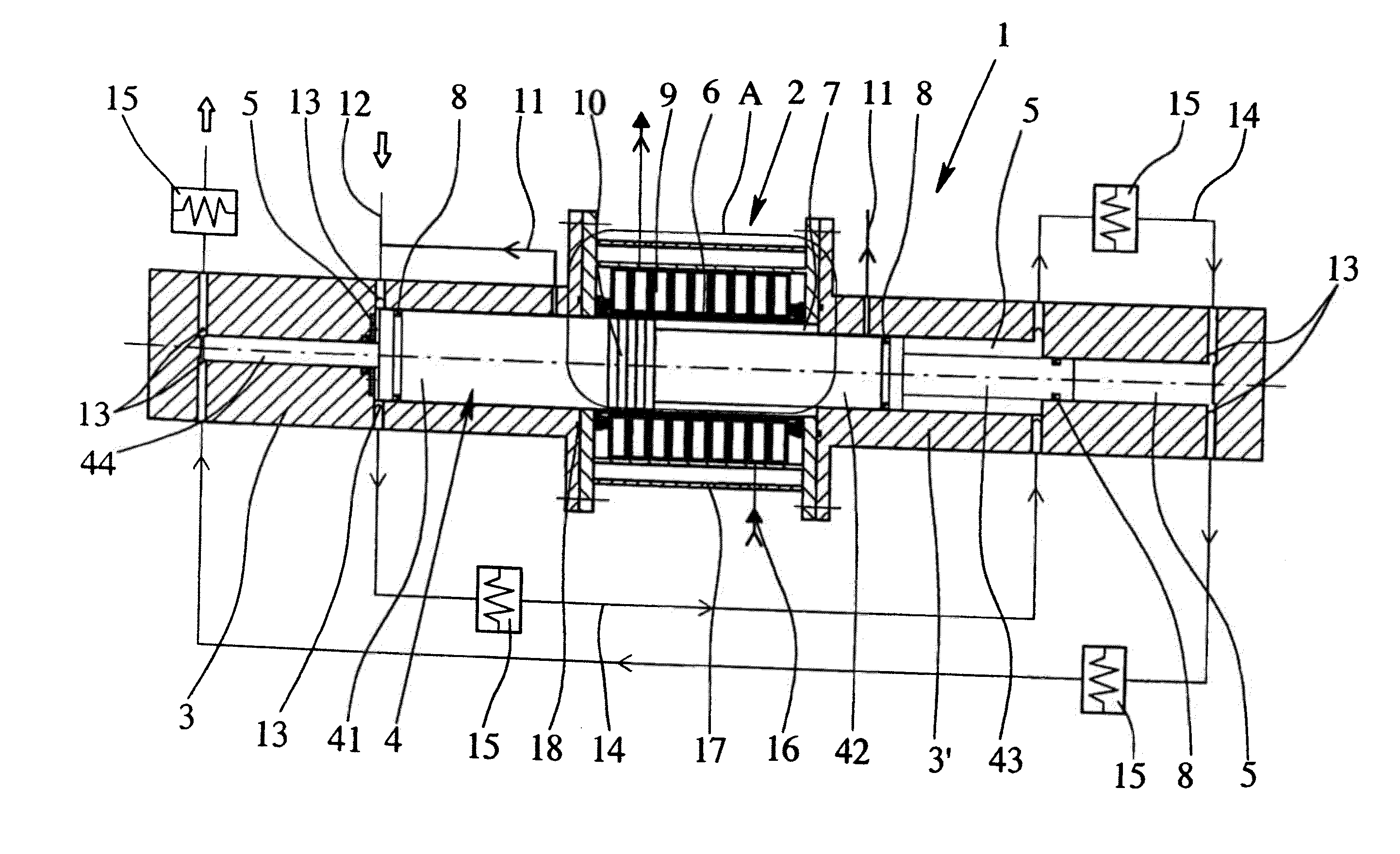
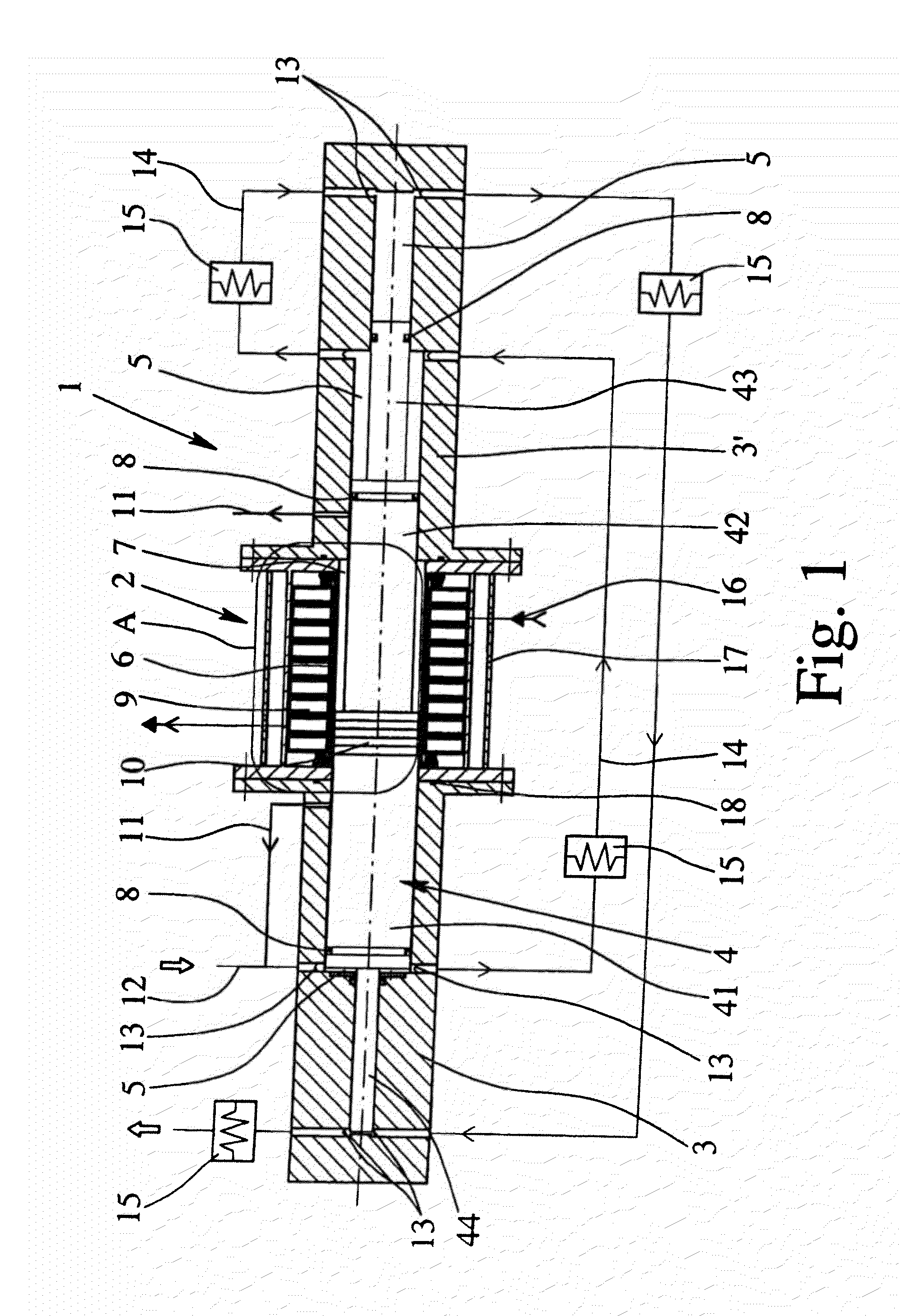
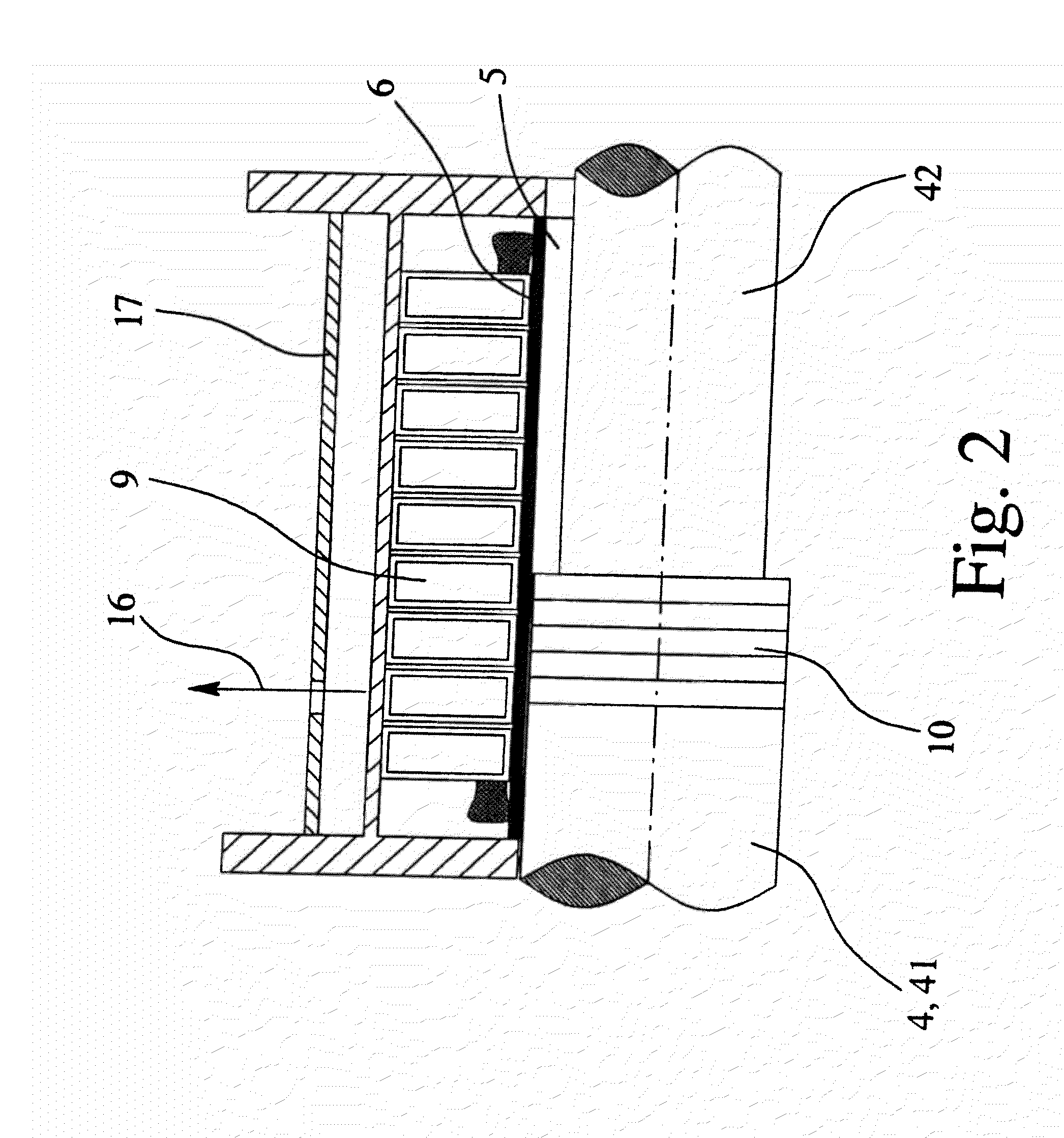
[0032]FIGS. 1, 3, 5 and 6 show four different embodiments of a fluid machine 1 in accordance with the invention, the figures being solely simplified representations, so that only the components important to the invention are shown. The fluid machines 1 shown in the figures are used for compressing gases, especially hydrogen, to a high pressure of 500 bar, for example. These fluid machines 1 can therefore advantageously be used especially for outfitting hydrogen filling stations.

[0033]The fluid machines 1 shown in FIGS. 1, 3, and 5 each have a linear motor 2 for driving a solid piston 4 which is movably located in a cylinder 3. By using the linear motor 2 as a drive, a translational driving force is applied to the solid piston 4 so that the solid piston 4 can move back and forth axially within the cylinder 3, 3′. Within the cylinder 3 is at least one compression space 5 for the gas to be compressed, the size of the compression space changing depending on the position of the solid pis...


PUM


Abstract

A fluid machine for compressing or conveying fluids, in particular for compressing gases to high pressures, has a linear motor (2), at least one cylinder (3), a solid or liquid piston (4, 4′) which can be moved axially in the cylinder (3), and at least one compression space (5) which is formed between the cylinder (3) and the solid or liquid piston (4, 4′), wherein the linear motor (2) applies translational driving force to the solid or liquid piston (4, 4′). For such a fluid machine, the leakage-free and lubricant-free compression and conveying of fluids, in particular a compression of gases to high pressures, and a rather simple construction is made possible owing to the fact that the solid or liquid piston (4, 4′) is surrounded in the area of the linear motor (2) by a firmly attached pipe section (6).

Description

BACKGROUND OF THE INVENTION[0001]1. Field of Invention[0002]The invention relates to a fluid machine for compressing or conveying fluids, especially for compressing gases to high pressures, with a linear motor, at least one cylinder, a solid piston which can be moved axially in the cylinder, or an axially movable liquid piston and at least one compression space which is made between the cylinder and the solid piston and the liquid piston, the linear motor transferring a translational driving force to the solid piston or the liquid piston.[0003]2. Description of Related Art[0004]Fluid machines are known in the prior art in different embodiments and versions. Fluid machines can be subdivided, first of all, according to whether they are intended for conveying or compressing liquids or gases. Fluid machines which are used for conveyance of liquids are generally also called pumps, while fluid machines for compressing gases are called compressors. Moreover fluid machines can also be disti...

Claims


Application Information

Patent Timeline
IPC IPC(8): F04B35/00
CPCF04B17/044F04B25/005F04B25/02F04F1/06F04B39/0011F04B39/06F04B39/064F04B35/045
Inventor DEHNEN, MANFREDHABEL, HEIKOSKAMEL, CHRISTOPHER
Owner ANDREAS HOFER HOCHDRUCKTECHN
Why Eureka
Try Eureka