
Method and apparatus for determining relative positioning between neurostimulation leads

a neurostimulation and relative positioning technology, applied in the field of tissue stimulation systems, can solve the problems of inability to easily find information for programmer, inability to accurately determine the position inability to accurately determine the effect of the neurostimulation lead,

Active Publication Date: 2011-03-03
BOSTON SCI NEUROMODULATION CORP
View PDF10 Cites 26 Cited by
  • Summary
  • Abstract
  • Description
  • Claims
  • Application Information

AI Technical Summary

Benefits of technology

[0018]An optional method comprises estimating additional pluralities of cross-lead electrical parameters to respectively generate an additional plurality of reference electrical profiles for the electrode leads in an additional plurality of known staggered configurations offset from each other by a distance less than one center-to-center electrode spacing, comparing the measured electrical profile to the additional reference electrical profiles, and quantifying the longitudinal stagger between the electrode leads based on the comparison between the measured electrical profile and the first, second, and additional reference electrical profiles. The distance that the additional known staggered configurations are offset from each other may be, e.g., predetermined or may be dynamically selected based on the comparison between the measured electrical profile and at least some of the additional reference electrical profiles.
[0019]In accordance with a second aspect of the present inventions, a neurostimulation control system for use with electrode leads is provided. The neurostimulation control system comprises a user interface configured for receiving an input from a user. The neurostimulation control system further comprises a processor configured for generating instructions to measure a plurality of cross-lead electrical parameters, generating a measured electrical profile of the electrode leads from the measured cross-lead electrical parameters, estimating a plurality of cross-lead electrical parameters to generate a first reference electrical profile for the electrode leads in a first known staggered configuration, spatially shifting the first reference electrical profile to generate a second reference electrical profile for the electrode leads in a second known staggered configuration, comparing the measured electrical profile to the first and second reference electrical profiles, and quantifying a longitudinal stagger between the electrode leads based on the comparison. The details of these processor functions can be the same as those described above with respect to the method. The external control device may further comprise a display for displaying the leads with the quantified longitudinal stagger. The neurostimulation control system may comprise an external control device containing the user interface and at least one processor. In this case, the neurostimulation control system may further comprise telemetry circuitry configured for wirelessly transmitting the instructions to a neurostimulator to measure the plurality of cross-lead electrical parameters. Alternatively, at least some of the processing capability can be incorporated into the neurostimulation device itself.

Problems solved by technology

Thus, correct lead placement can mean the difference between effective and ineffective pain therapy.
Such information, however, is not readily available to the programmer unless fluoroscopic imaging is performed.
Fluoroscopic imaging involves ionized radiation, adds time and cost, and requires a bulky instrument, both of which may limit its use in the clinical setting, and effectively prevent its use outside of the clinical setting.
If such lead placement is not detected in a timely manner before the system is fully implanted, it may result in inefficient therapy and possibly require a second surgery for lead revision.
Thus, lead migration continues to be the most common technical complication of spinal cord stimulation therapy.
Although the comparison of the measured field potential profile to numerous reference profiles generated by the FEM model is computationally intensive and requires a lot of memory, the CP is embodied in a computer with the processing power and memory necessary to efficiently perform these computations.
This presents a potential difficulty in transferring the present EGL Scan features directly into a RC, because it requires memory space for the database storage that may not be available in the RC.

Method used


Image

  • Method and apparatus for determining relative positioning between neurostimulation leads
  • Method and apparatus for determining relative positioning between neurostimulation leads
  • Method and apparatus for determining relative positioning between neurostimulation leads

Examples


Embodiment Construction

[0032]The description that follows relates to a spinal cord stimulation (SCS) system. However, it is to be understood that while the invention lends itself well to applications in SCS, the invention, in its broadest aspects, may not be so limited. Rather, the invention may be used with any type of implantable electrical circuitry used to stimulate tissue. For example, the present invention may be used as part of a multi-lead system such as a pacemaker, a defibrillator, a cochlear stimulator, a retinal stimulator, a stimulator configured to produce coordinated limb movement, a cortical stimulator, a deep brain stimulator, peripheral nerve stimulator, microstimulator, or in any other neural stimulator configured to treat urinary incontinence, sleep apnea, shoulder sublaxation, headache, etc.

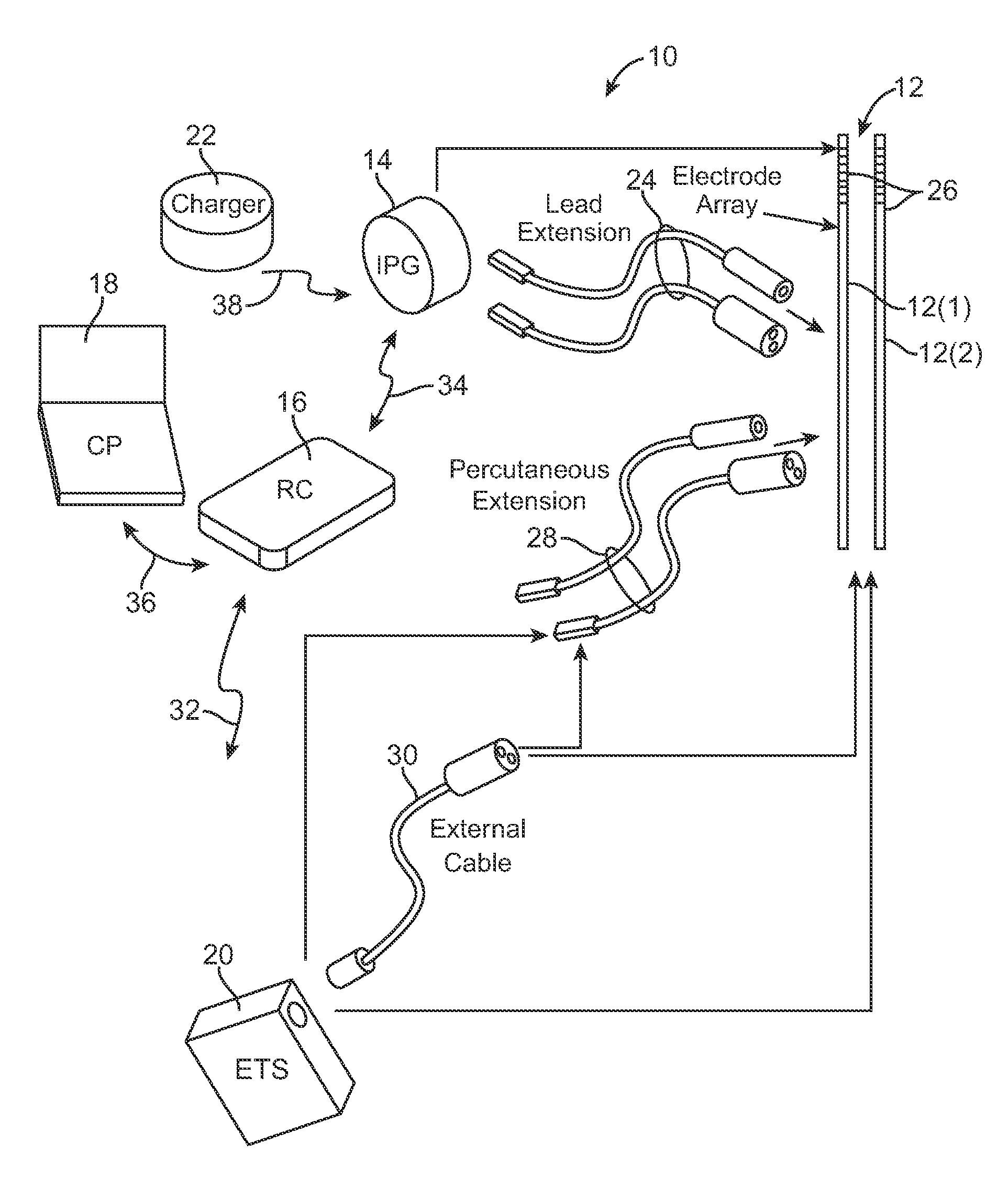
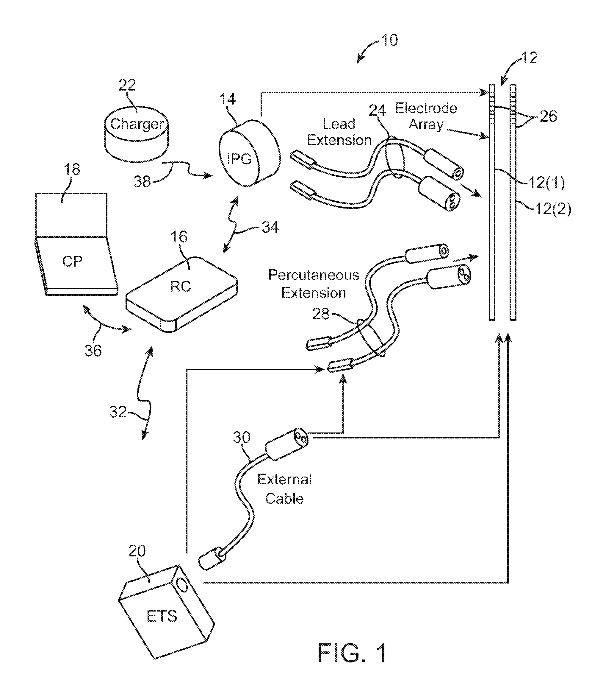
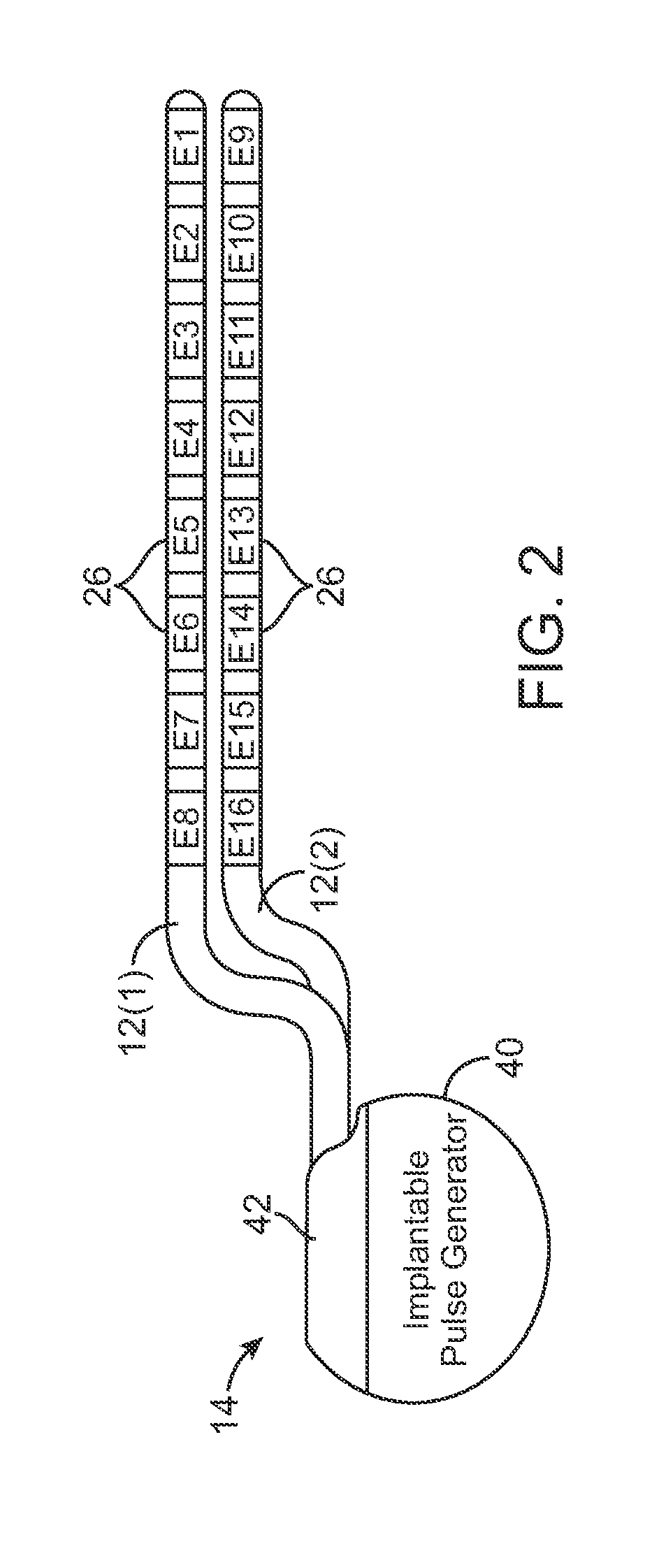
[0033]Turning first to FIG. 1, an exemplary SCS system 10 generally comprises a plurality of percutaneous leads 12 (in this case, two percutaneous leads 12(1) and 12(2)), an implantable pulse gener...


PUM


Abstract

A method and neurostimulation control system for operating two leads disposed adjacent tissue of a patient are provided. A plurality of cross-lead electrical parameters are measured to generate a measured electrical profile of the electrode leads. A plurality of cross-lead electrical parameters are estimated to generate a first reference electrical profile for the electrode leads in a first known staggered configuration. The first reference electrical profile is spatially shifted to generate a second reference electrical profile for the electrode leads in a second known staggered configuration. The measured electrical profile is compared to the first and second reference electrical profiles, and a longitudinal stagger between the electrode leads is quantified based on the comparison.

Description

FIELD OF THE INVENTION[0001]The present invention relates to tissue stimulation systems, and more particularly, to apparatus and methods for determining the position of neurostimulation leads.BACKGROUND OF THE INVENTION[0002]Implantable neurostimulation systems have proven therapeutic in a wide variety of diseases and disorders. Pacemakers and Implantable Cardiac Defibrillators (ICDs) have proven highly effective in the treatment of a number of cardiac conditions (e.g., arrhythmias). Spinal Cord Stimulation (SCS) systems have long been accepted as a therapeutic modality for the treatment of chronic pain syndromes, and the application of tissue stimulation has begun to expand to additional applications such as angina pectoralis and incontinence. Deep Brain Stimulation (DBS) has also been applied therapeutically for well over a decade for the treatment of refractory chronic pain syndromes, and DBS has also recently been applied in additional areas such as movement disorders and epilep...

Claims


Application Information

Patent Timeline
Patent Type & Authority Applications(United States)
IPC IPC(8): A61N1/08
CPCA61B5/053A61N1/0553A61N1/37247A61N1/37241A61N1/05A61N1/36182A61N2001/083A61B5/065A61N1/3603
Inventor ZHU, CHANGFANGMOFFITT, MICHAEL
Owner BOSTON SCI NEUROMODULATION CORP
Learn More