Shielded network for an active medical device implantable lead

a shielded network and active medical device technology, applied in the field of high frequency energy induced onto implantable leads, can solve the problems of overheating of said lead or its associated electrode, brain damage or multiple amputations, overheating of the associated interface with body tissue, etc., and achieves low resistance loss, high equivalent series resistance, and high resistance loss

Inactive Publication Date: 2011-03-03
WILSON GREATBATCH LTD
View PDF9 Cites 57 Cited by
  • Summary
  • Abstract
  • Description
  • Claims
  • Application Information

AI Technical Summary

Benefits of technology

[0028]The overall Q of the bandstop filter is selected to balance impedance at the selected frequency versus frequency bandwidth characteristics. When the Q of the inductive component is relatively high, the Q of the capacitive component is relatively low such that the inductive component has a relatively low resistive loss and the capacitive component has a relatively high equivalent series resistance. When the Q of the inductive component is relatively low and the Q of the capacitive component is relatively high, the inductive component has a relatively high resistive loss and the capacitive component has a relatively low equivalent series resistance.

Problems solved by technology

It has been documented that when this current becomes excessive, overheating of said lead or its associated electrode or overheating of the associated interface with body tissue can occur.
There have been cases of damage to such body tissue which has resulted in loss of capture of cardiac pacemaking pulses or tissue damage severe enough to result in brain damage or multiple amputations, and the like.
Electromagnetic interference (EMI) is also a significant issue.
In the past, there have been problems with microwave ovens, cell phones, and the like.
Stray signals that are picked up on implanted leads can be coupled to the interior of the AMD and interfere with sensitive electronic circuits.
In cardiac pacemakers, instances of EMI being detected as normal cardiac rhythms have resulted in pacemaker inhibition which can be life-threatening.
There have been reports of latent problems with cardiac pacemakers or other AMDs after an MRI procedure, sometimes occurring many days later.
Moreover, there are a number of papers that indicate that the SAR level is not entirely predictive of the heating that would be found in implanted leads or devices.
It is speculated that SAR level alone is not a good predictor of whether or not an implanted device or its associated lead system will overheat.
The effects of this heating are not readily detectable by monitoring during the MRI.
Such long term heating effects of MRI have not been well studied yet for all types of AMD lead geometries.
There can also be localized heating problems associated with various types of electrodes in addition to tip electrodes.
Variations in the pacemaker lead length and implant trajectory can significantly affect how much heat is generated.
Most experts still conclude that MRI for the pacemaker patient should not be considered safe.
It is well known that many of the undesirable effects in an implanted lead system from MRI and other medical diagnostic procedures are related to undesirable induced EMFs in the lead system and / or RF currents in its distal tip (or ring) electrodes.
This can lead to overheating of body tissue at or adjacent to the distal tip.
Excessive current at the distal electrode to tissue interface can cause excessive heating to the point where tissue ablation or even perforation can occur.
This can be life-threatening for cardiac patients.
For neurostimulator patients, such as deep brain stimulator patients, thermal injury can cause permanent disability or even be life threatening.
Similar issues exist for spinal cord stimulator patients, cochlear implant patients and the like.

Method used


Image

  • Shielded network for an active medical device implantable lead
  • Shielded network for an active medical device implantable lead
  • Shielded network for an active medical device implantable lead

Examples


Embodiment Construction

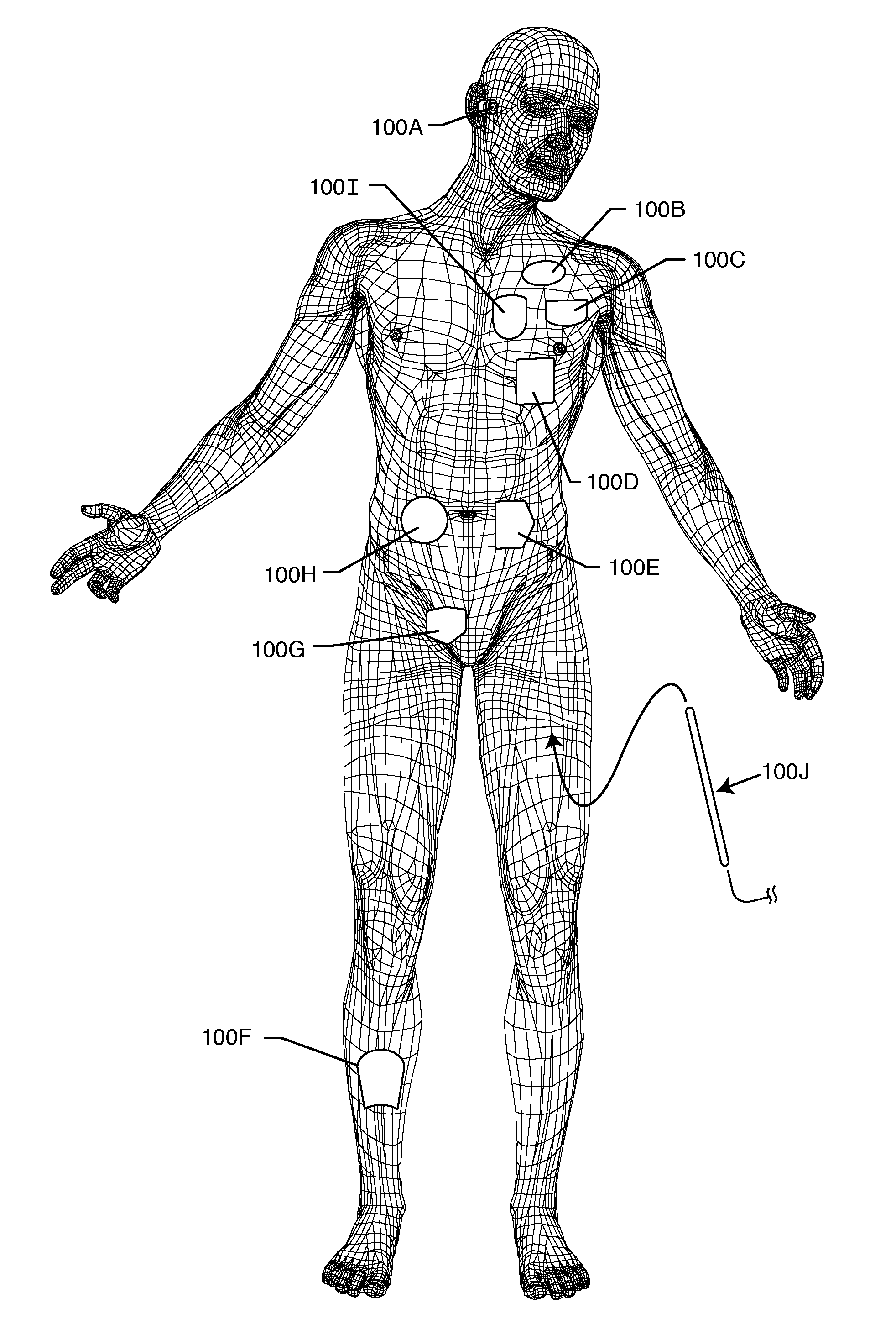
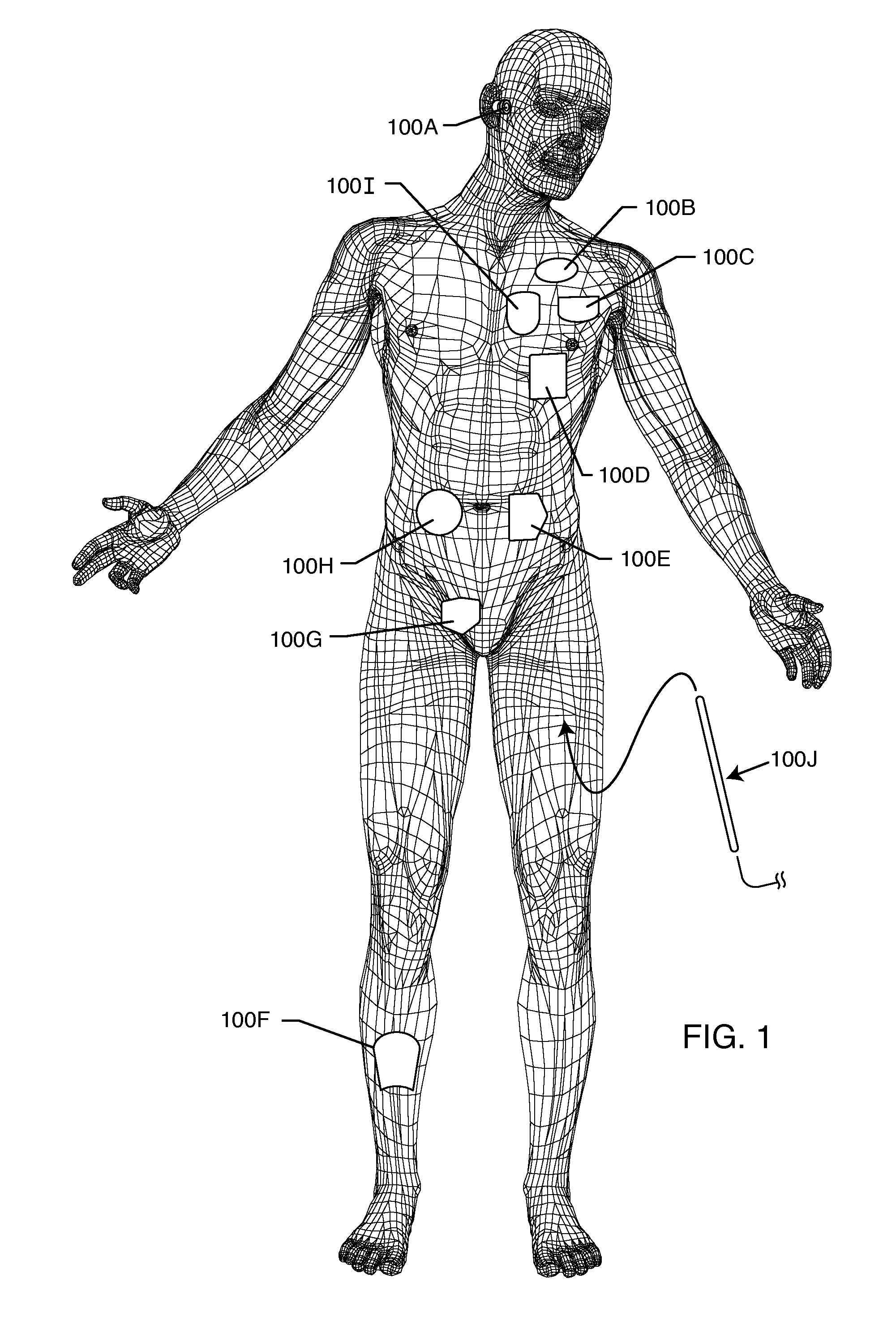
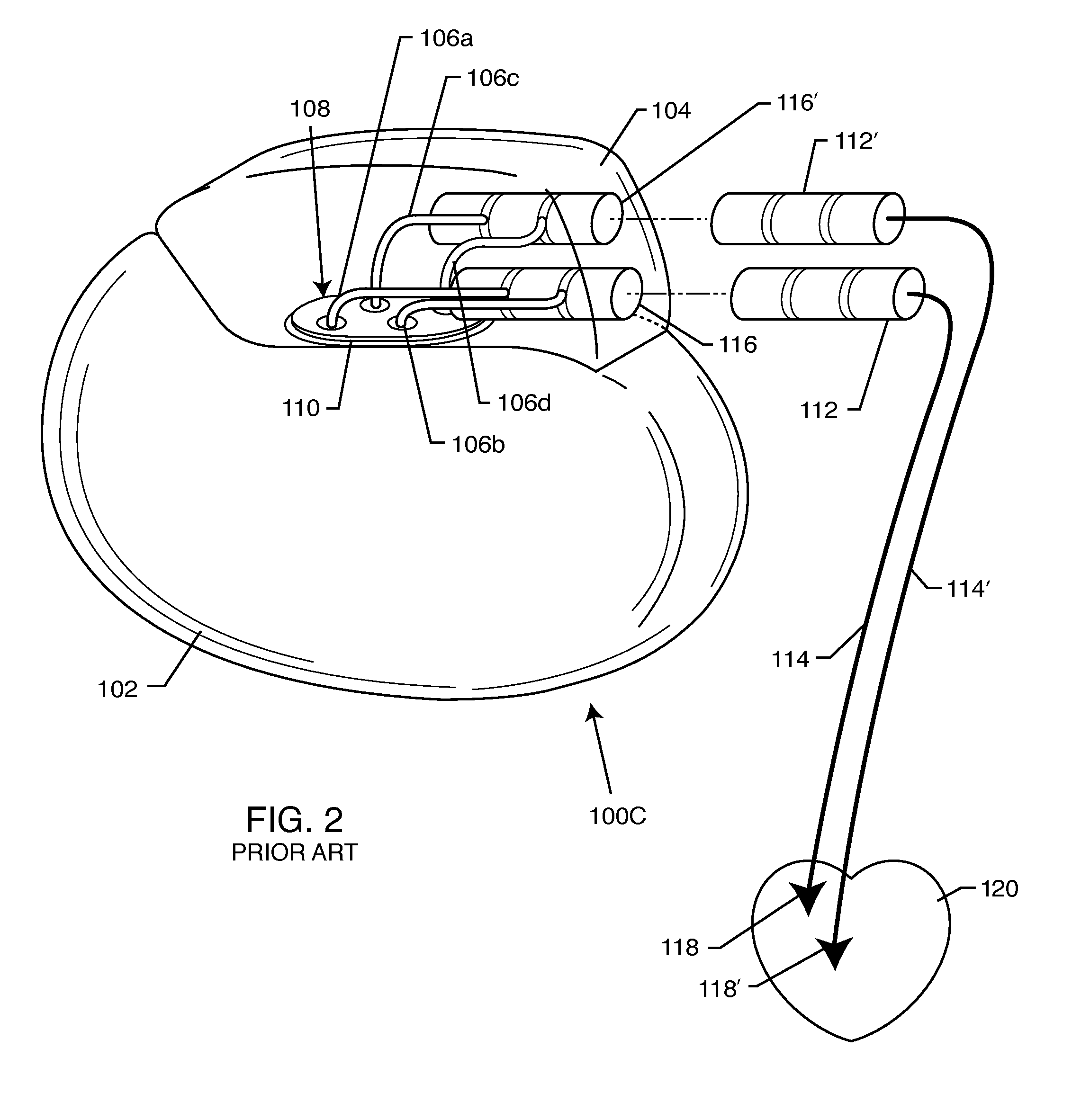
[0108]As shown in the drawings for purposes of illustration, the present invention relates to a system for RF shielding of a passive component or network disposed along the length of implanted leads of active medical devices (AMDs). In particular, the RF shielding is to shield a passive inductor or inductive component in the presence of high power electromagnetic field environments, such as the RF pulsed fields produced by a clinical MRI scanner. In a broad sense, the present invention comprises an active medical device system including an implanted lead having RF shielded inductors or passive network components including inductors. The implanted lead may be coaxial, rectangular, flat or other geometries. US 2009 / 0243756 incorporated herein by reference. Furthermore, the implanted lead may consist of a number of internal conductors, such as a bipolar lead for cardiac pacemaker channel or even an eight or sixteen conductor spinal cord stimulator implanted lead. This is also known as ...


PUM


Abstract

A shielded component or network for an active medical device (AMD) implantable lead includes (1) an implantable lead having a length extending from a proximal end to a distal end, all external of an AMD housing, (2) a passive component or network disposed somewhere along the length of the implantable lead, the passive component or network including at least one inductive component having a first inductive value, and (3) an electromagnetic shield substantially surrounding the inductive component or the passive network. The first inductive value of the inductive component is adjusted to a account for a shift in its inductance to a second inductive value when shielded.

Description

FIELD OF THE INVENTION[0001]This invention generally relates to the problem of high frequency energy induced onto implanted leads during medical diagnostic procedures such as magnetic resonant imaging (MRI). More specifically, the present invention relates to an implantable medical system comprised of an active medical device (AMD) and at least one lead extending exteriorly from a proximal end at or adjacent to the AMD, to a biological sensing or stimulating electrode at a distal end. The lead has a passive component or network, including at least one inductive component disposed somewhere along its length between the proximal end and distal end. At least the inductive component of the passive component or network is electromagnetically shielded.BACKGROUND OF THE INVENTION[0002]The radio frequency (RF) pulsed field of MRI can couple to an implanted lead in such a way that electromagnetic forces (EMFs) are induced in the lead. The amount of energy that is induced is related to a numb...

Claims


Application Information

Patent Timeline
Patent Type & Authority Applications(United States)
IPC IPC(8): A61N1/05
CPCA61N1/0551A61N1/05A61N1/3718A61N2001/086H01F17/00H01F27/36H01F2017/065H03H1/0007H03H7/0115H03H2001/0042H03H2007/013H03H7/1758H03H7/1766A61N1/057G01R33/285A61N1/08G01R33/288A61N1/056A61N1/086H01F27/363H01F27/366
Inventor DABNEY, WARREN S.JOHNSON, ROBERT SHAWNMOSCHIANO, HOLLY NOELLESTEVENSON, ROBERT A.HALPERIN, HENRY R.LARDO, ALBERT C.
Owner WILSON GREATBATCH LTD
Why Eureka
Try Eureka