Oil mist separator for internal combustion engine

a technology of oil mist separator and internal combustion engine, which is applied in the direction of lubricant mounting/connection, lubrication elements, pressure lubrication, etc., can solve the problems of clogging of porous filter, separator not separating enough oil, and significant acceleration of oil deterioration, so as to prevent the occurrence of a malfunction and efficiently separate an oil component

Inactive Publication Date: 2011-03-10
TOYOTA JIDOSHA KK
View PDF25 Cites 27 Cited by
  • Summary
  • Abstract
  • Description
  • Claims
  • Application Information

AI Technical Summary

Benefits of technology

[0021]With the invention, it is possible to efficiently separate an oil component from

Problems solved by technology

It is known that when so-called blow-by gas, containing unburned fuel, that leaks through the gap between a piston and a cylinder into a crankcase is mixed with the oil in the crankcase, so-called sludge is produced, which significantly accelerates the deterioration of the oil.
However, there is a problem that such an oil mist separator does not effect sufficie

Method used


Image

  • Oil mist separator for internal combustion engine
  • Oil mist separator for internal combustion engine
  • Oil mist separator for internal combustion engine

Examples


Embodiment Construction

[0029]An example embodiment of the invention will be described below with reference to the attached drawings.

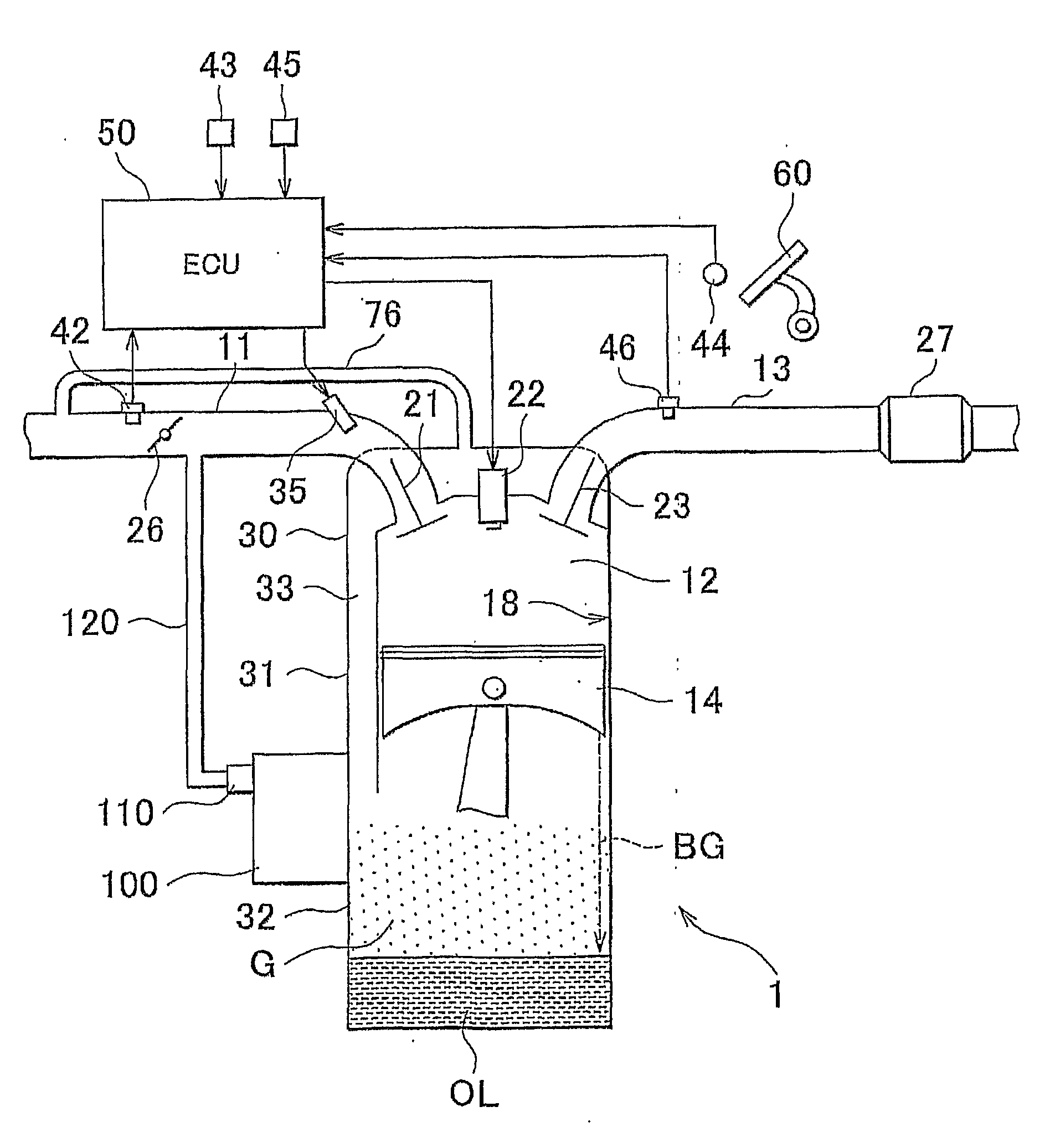
[0030]FIG. 1 is a schematic configuration diagram of an internal combustion engine in which an oil mist separator according to an embodiment of the invention is used.

[0031]The internal combustion engine 1 includes a cylinder head 30, a cylinder block 31, and a crankcase 32 formed integrally with the cylinder block 31. In addition, the internal combustion engine 1 has an intake passage 11 for introducing intake air into the cylinder head 30 and an exhaust passage 13 for discharging exhaust gas from the cylinder head 30.

[0032]The internal combustion engine 1 further includes: a rotation speed sensor 43 that detects a rotation speed of a crankshaft (not shown); a water temperature sensor 45 that detects a temperature of cooling water for cooling the cylinder block 31; an intake air amount sensor 42 that is provided in the intake air passage 11 and detects the amount of intake ai...


PUM


Abstract

An oil mist separator (100) for an internal combustion engine that separates an oil component in a gas, which is introduced from a crankcase of the internal combustion engine, from the gas, includes a porous filter (150) that separates, from the gas, the oil component in the gas, the porous filter (150) being provided in a passage, through which the gas passes, and being coated with a counteragent for neutralizing an acid substance.

Description

BACKGROUND OF THE INVENTION[0001]1. Field of the Invention[0002]The invention relates to an oil mist separator for an internal combustion engine.[0003]2. Description of the Related Art[0004]It is known that when so-called blow-by gas, containing unburned fuel, that leaks through the gap between a piston and a cylinder into a crankcase is mixed with the oil in the crankcase, so-called sludge is produced, which significantly accelerates the deterioration of the oil. The main components of sludge are olefin (hydrocarbon) in the oil, and NOx and water in the blow-by gas, and such main components react with the help of heat and acid to produce a sludge precursor and a sludge binder, which in turn produce the sludge. Sludge looks to be a mud-like substance.[0005]A positive crankcase ventilation (PCV) system is available that, in order to suppress deterioration of oil, introduces the blow-by gas in the crankcase into the inlet system to combust the unburned fuel in the blow-by gas (see Jap...

Claims


Application Information

Patent Timeline
IPC IPC(8): F01M11/03
CPCF01M9/02F01M2013/0438F01M13/04
Inventor KOYAMAISHI, NAOTOSUZUKI, TETSUSHIMURAKAMI, MOTOICHIINAMI, NORIOKOIKE, RYUJI
Owner TOYOTA JIDOSHA KK
Why Eureka
Try Eureka