Battery system with a current detection circuit

a current detection and battery technology, applied in the direction of engine-driven generators, instruments, transportation and packaging, etc., can solve the problems of battery not being driven by batteries, current detection circuit not being able to determine if, absence of current flow cannot be distinguished from open-circuited current detection lines, etc., to reliably detect open-circuit, simple circuit structure, reliable and stable detection of battery curren

Active Publication Date: 2011-03-10
SANYO ELECTRIC CO LTD
View PDF6 Cites 26 Cited by
  • Summary
  • Abstract
  • Description
  • Claims
  • Application Information

AI Technical Summary

Benefits of technology

[0010]The battery system described above has the characteristic that it can detect current detection line open-circuit and can reliably and stably detect battery current with a simple circuit structure. This is because a test voltage is supplied to the input-side of the amplifier that amplifies the voltage induced across the current detection resistor, and the detection circuit that detects amplifier output voltage compares the amplifier output voltage with the reference voltage to detect current detection line open-circuit by the voltage shift from the reference voltage. This battery system detects current detection line open-circuit when no battery current is flowing. When there is no open-circuit in the current detection lines, the low resistance current detection resistor is connected to the input-side of the amplifier and the voltage input to the detection circuit is within the range of the reference voltage. When there is an open-circuit in the current detection lines, the low resistance current detection resistor is disconnected from the input-side of the amplifier and the voltage input to the detection circuit is not equal to the reference voltage. Therefore, the detection circuit can reliably detect a

Problems solved by technology

This is because the vehicle cannot be driven by the batteries when the battery current cannot be detected.
This current detection circuit cannot determine if there is an open-circuit in the current detection lines that connect the current detection resist

Method used


Image

  • Battery system with a current detection circuit
  • Battery system with a current detection circuit
  • Battery system with a current detection circuit

Examples


Embodiment Construction

)

[0028]The following describes embodiments of the present invention based on the figures.

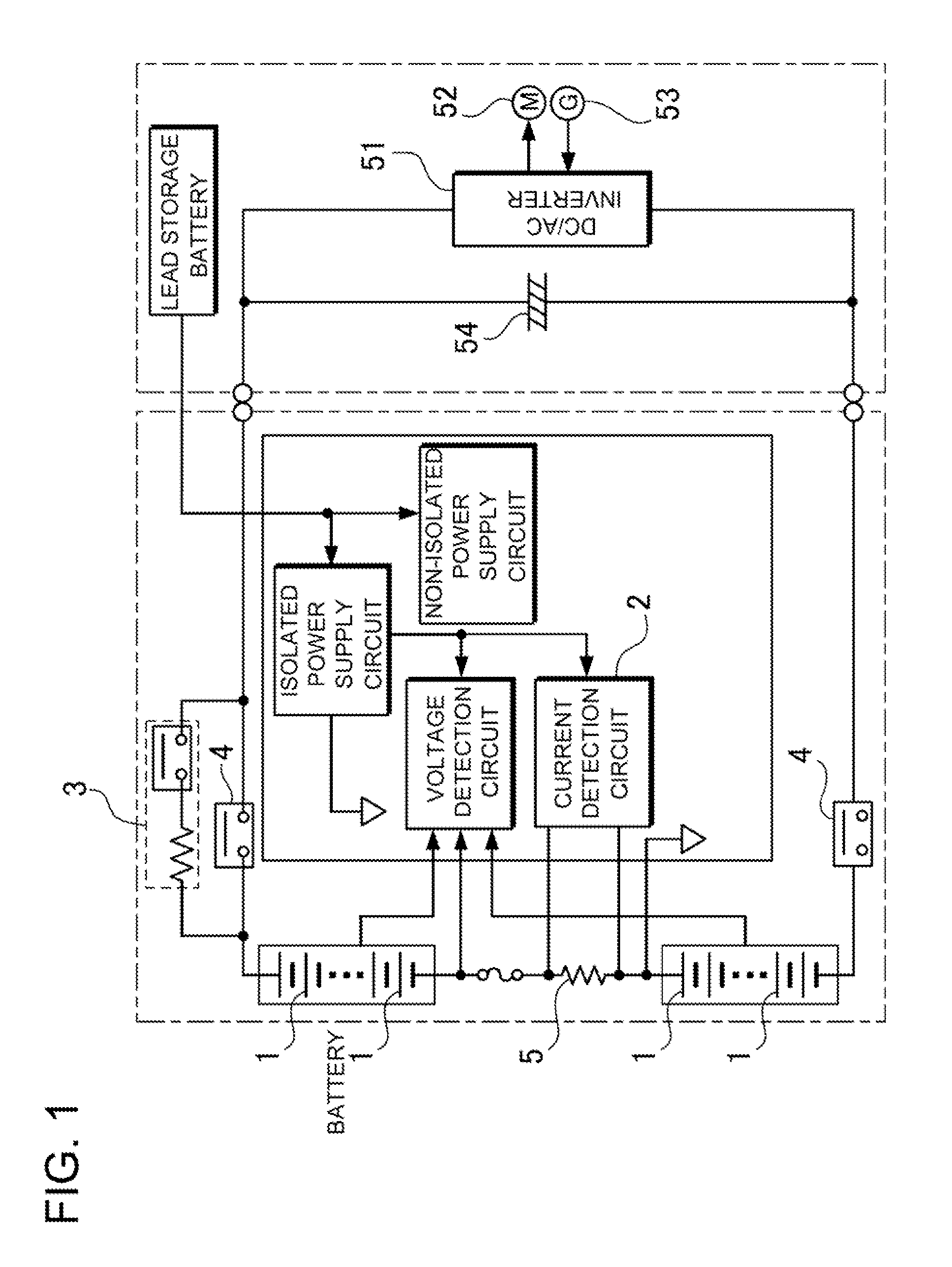
[0029]FIG. 1 shows a battery system used as a car power source apparatus and more particularly used as a power source apparatus on-board a hybrid car. This battery system detects charging and discharging current of batteries 1 discharged by supplying power to a motor 52 that drives the car, and charged by a generator 53 driven by an engine and regenerative braking. However, the battery system of the present invention is not limited to use as a car power source apparatus. This is because the battery system can be used in any battery system application that detects current with high reliability.

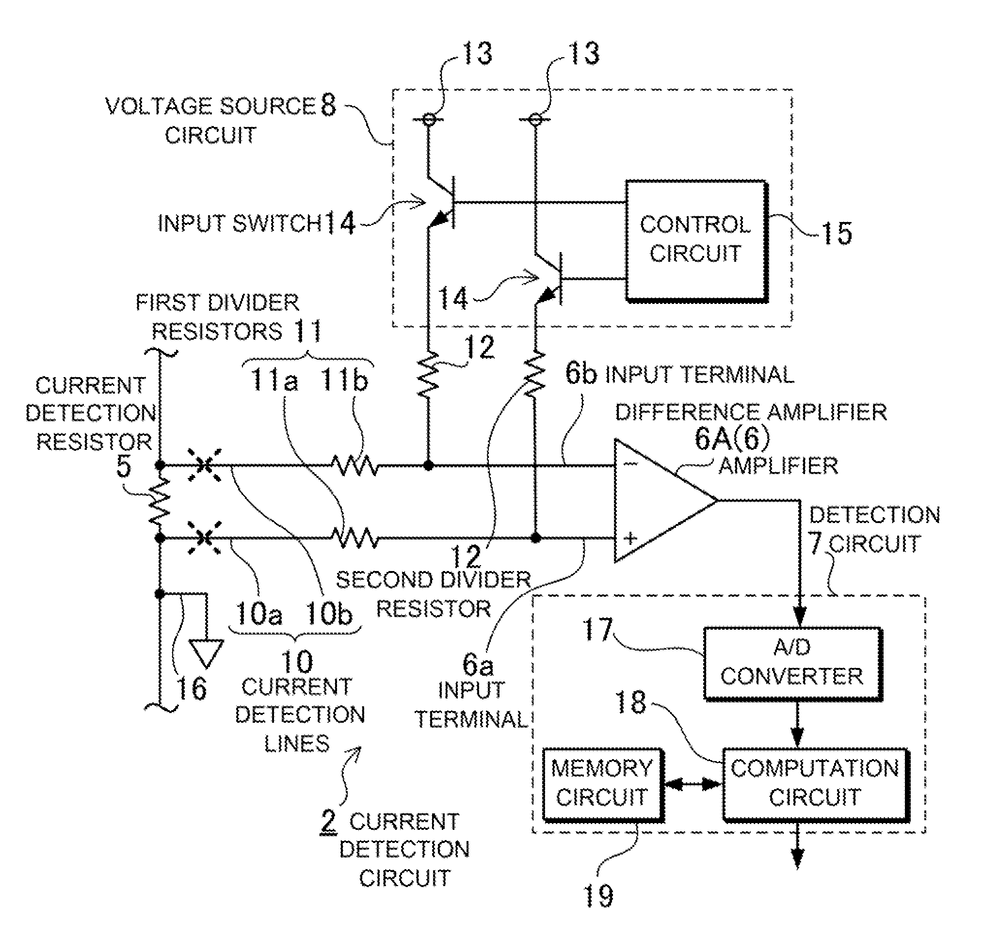
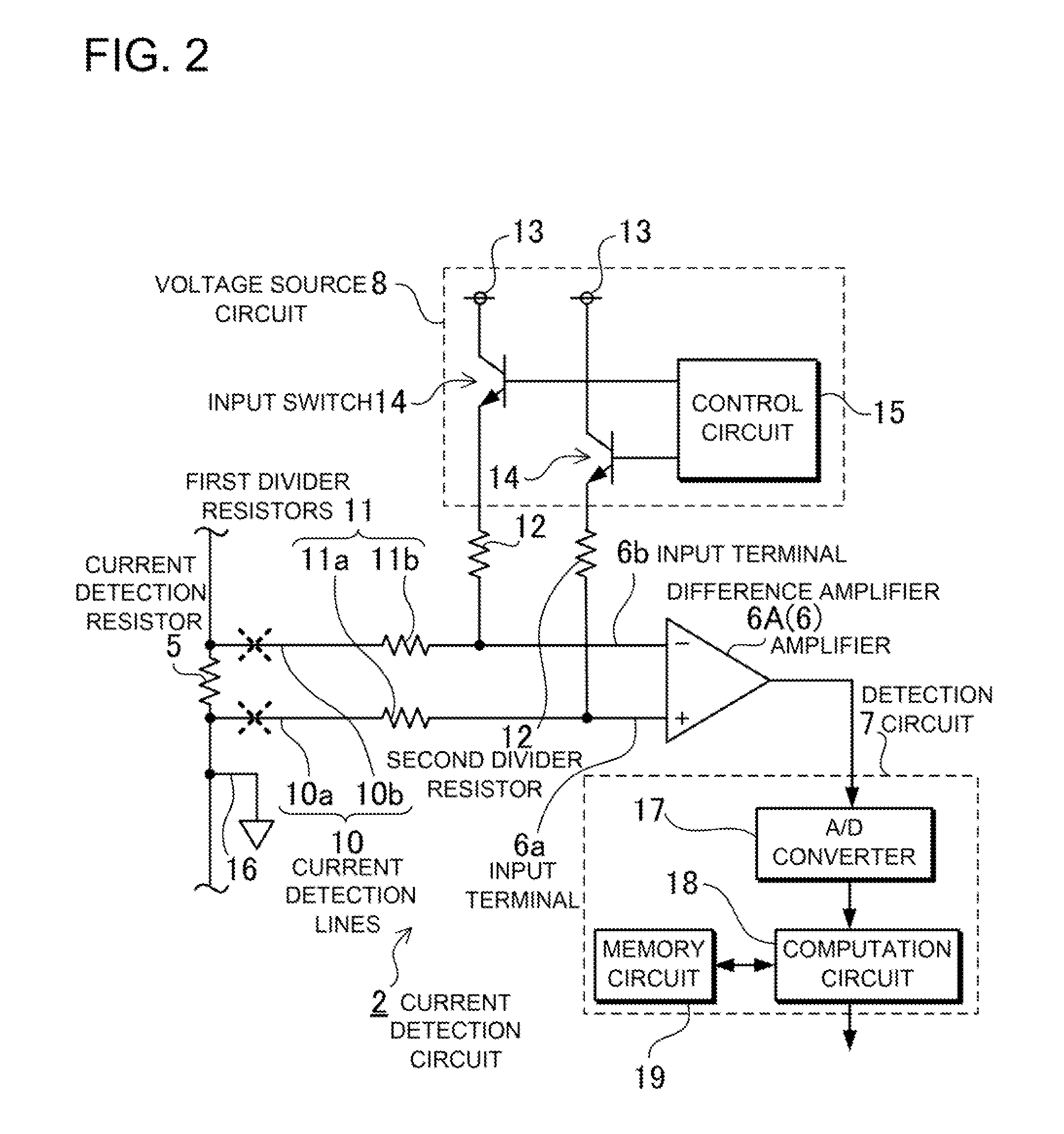
[0030]The battery system of FIG. 1 is provided with a current detection circuit 2 that detects current flowing through the batteries 1; main relays 4 that connect the batteries 1 to the direct current-to-alternating current (DC / AC) inverter 51, which is the vehicle-side load; and a pre-charge circuit 3 that...


PUM


Abstract

The battery system has a current detection circuit 2, an amplifier 6, and a detection circuit 7 that detects the current flowing through batteries 1 from amplifier 6 output. The current detection circuit 2 is provided with a voltage source circuit 8 that supplies a test voltage to the input-side of the amplifier 6. Current detection lines 10 connect the current detection resistor 5 to the input-side of the amplifier 6, and the detection circuit 7 stores a reference voltage corresponding to the current detection lines 10 in the connected state. When the voltage source circuit 8 supplies the test voltage to the input-side of the amplifier 6, the detection circuit 7 compares the amplifier 6 output voltage with the reference voltage. The detection circuit 7 detects an open-circuit in the current detection lines 10 by the shift in voltage from the reference voltage.

Description

BACKGROUND OF THE INVENTION[0001]1. Field of the Invention[0002]The present invention relates to a battery system with a current detection circuit capable of extremely reliable current detection, and in particular relates to a battery system with a current detection circuit used as a power source apparatus in a vehicle such as a hybrid car or electric automobile (electric vehicle) optimally suited for stably detecting battery charging and discharging current.[0003]2. Description of the Related Art[0004]In a power source apparatus used in a vehicle such as a hybrid car, high reliability and high precision detection of battery charging and discharging current is in demand. This is because the vehicle cannot be driven by the batteries when the battery current cannot be detected. A state-of-the-art current detection circuit uses a difference amplifier to amplify the voltage across a current detection resistor in series with the batteries, and detects current from the output voltage of t...

Claims


Application Information

Patent Timeline
IPC IPC(8): G01N27/416G01R19/00G01R31/36H02J7/00H02J7/02
CPCB60L7/10B60L11/02G01R31/026G01R31/3658Y02T10/70H02J7/0021G01R31/3648Y02T10/7055Y02T10/7077G01R31/396B60L50/10G01R31/54G01R31/52Y02T10/7072H02J7/0013H02J7/0047
Inventor YUGOU, MASAKIFURUKAWA, KIMIHIKOYAMAUCHI, YUTAKA
Owner SANYO ELECTRIC CO LTD
Why Eureka
Try Eureka