Linear light source having light guide with taped saw tooth structures

a technology of taped saw tooth and light guide, which is applied in the direction of shaving accessories, lighting and heating apparatus, instruments, etc., can solve the problems of reducing the scanning resolution or uneven reflection of document light, affecting the accuracy of scanning, and the light intensity ejected around the peripheral of the pickup lens becomes weaker relative to the center of the pickup lens, etc., to achieve the effect of improving the prior art drawbacks, high fabrication cost, and complicated control operations

Inactive Publication Date: 2011-03-10
E PIN OPTICAL IND
View PDF9 Cites 7 Cited by
  • Summary
  • Abstract
  • Description
  • Claims
  • Application Information

AI Technical Summary

Benefits of technology

[0014](1) by means of the light guide with taped saw tooth structures and arrangement of LED light sources on the incident surfaces at two sides of the light guide according to the present invention, it is possible to improve the prior art drawbacks of high fabrication cost due to direct illumination with a plurality of LED light sources and complicated control operations;
[0015](2) through the taped saw tooth structures in the light guide according to the present invention, it is possible to form a linearly converged illumination distribution in the main scanning direction and a U-shaped illumination distribution in the sub scanning direction, so as to complementarily compensate the phenomenon of weaker light intension on the peripheral of CCD, thus facilitating formation of image signals have uniform light intensity;
[0016](3) by disposing the structure of concave optical surface on the ejective surface or disposing the structure of concave optical surfaces on the incident surfaces in the light guide according to the present invention, it is possible to increase the usage of light and accordingly enhance the light intensity.

Problems solved by technology

However, because of requirement on additional voltage transformers and inconsistency against environment protection regulations due to inclusion of halogen, it has be gradually replaced by Light Emitting Diodes (LEDs); for example, US Patent US2004 / 0095620 disclosed a light source using the LED for scanners.
The LED provides advantages of power saving and long lifespan; whereas the lambert distribution (said illumination distribution in general) of the light source using the LED for scanners is less uniform than the CCFL, causing reduced scanning resolution or uneven reflection light from the document.
As a result, it can be only applied in low-speed scanners.
However, due to the effect of the optical surfaces of the pickup lens, the reflected light from document is incident into the pickup lens and focused by the pickup lens, light intensity ejected around the peripheral of the pickup lens becomes weaker relative to the center of the pickup lens.
The uniform illumination in the sub scanning direction of the light source may thus result in less brightness at the edge of document images, and resolution of the scanner is undesirably reduced.
But such a technical approach applying installation of LED array and the like on the rear side of light guide may require multiple LED elements and complicated control operations.
Whereas, different tooth shape and tooth pitch may cause difficulties in manufacture processes, leading to undesirable high fabrication costs.

Method used


Image

  • Linear light source having light guide with taped saw tooth structures
  • Linear light source having light guide with taped saw tooth structures
  • Linear light source having light guide with taped saw tooth structures

Examples


first embodiment

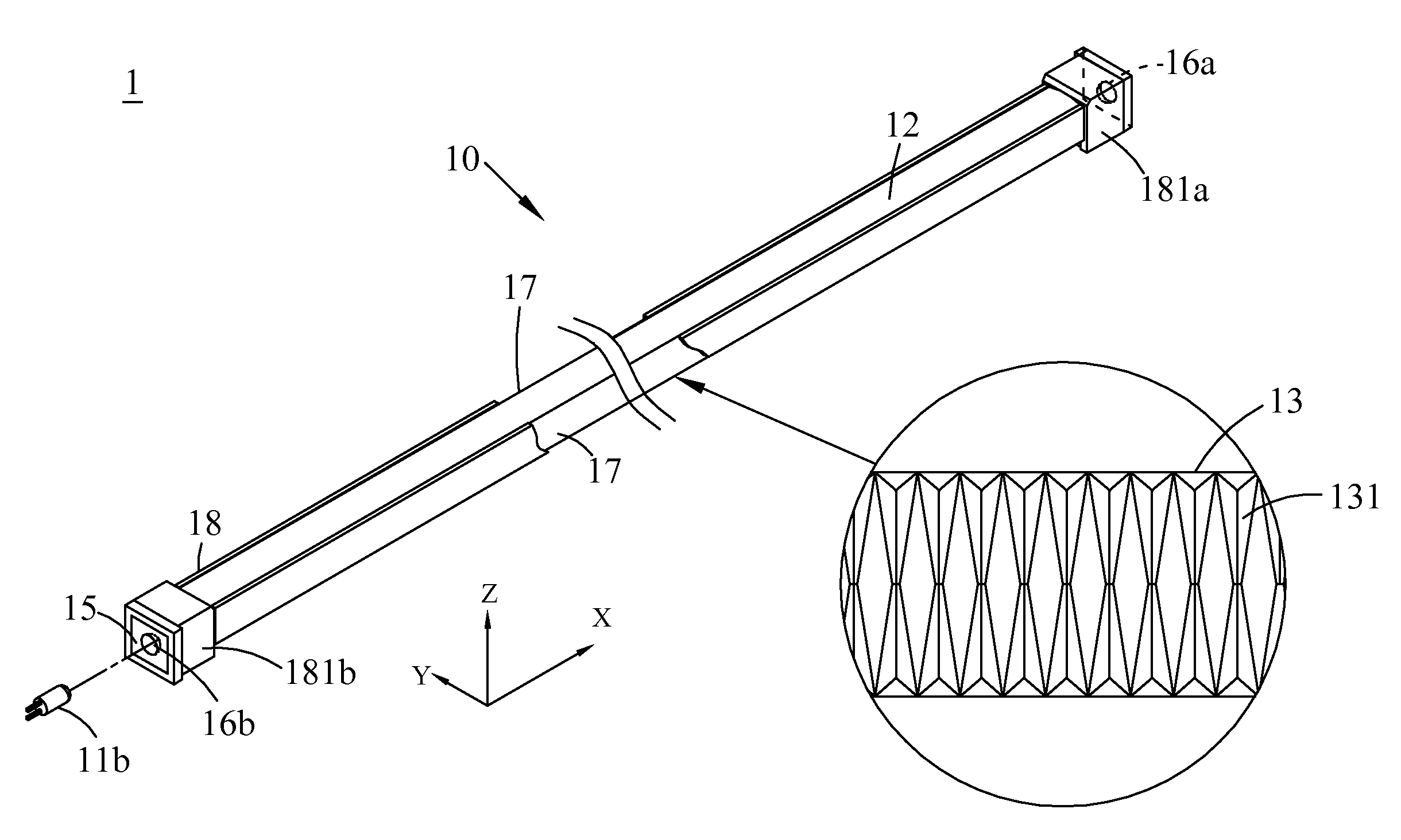
[0050]Refer now to FIG. 5, wherein a diagram of the linear light source having a light guide with the taped saw tooth structures for the present embodiment is shown. In the present embodiment, the light guide 10 is made of an optical material, Polycarbonates (PC), refractive index nd=1.58, and the incident surfaces 15 is a plane and the ejective surface 12 is a plane in the sub scanning direction. Relevant parameters for such a light guide 10 are illustrated in the following Table 1.

TABLE 1Relevant Parameters for Light Guide according to First EmbodimentRefractive Index nd1.58Curvature Radius of Ejective Surface in−10.13Main Scanning Direction R12Y (mm)Curvature Radius of Ejective Surface in Sub∞scanning Direction R12X (mm)Chamfer Surface Angle θc (deg.)37.5Projection Length of Chamfer Surface in0.55Main Scanning Direction c (mm)Distance between Two Taped Saw Teeth d0.55(mm)Length from Bottom of Taped Saw Teeth to6.84Apex of Ejective Surface Hz (mm)

second embodiment

[0051]Refer to FIG. 13, wherein a diagram of the linear light source having a light guide with the taped saw tooth structures for the present embodiment is shown. In the present embodiment, the light guide 10 is made of an optical material, Polycarbonates (PC), refractive index nd=1.58, and the incident surface 15 is a concave optical surface 16 and the ejective surface 12 is a plane in the sub scanning direction. Relevant parameters for such a light guide 10 are illustrated in the following Table 2.

TABLE 2Relevant Parameters for Light Guide according to Second EmbodimentRefractive Index nd1.58Curvature Radius of Ejective Surface in −10.13Main Scanning Direction R12Y (mm)Curvature Radius of Ejective Surface in Sub∞scanning Direction R12X (mm)Chamfer Surface Angle θc (deg.)45Projection Length of Chamfer Surface in0.49Main Scanning Direction c (mm)Distance between Two Taped Saw Teeth d0.5(mm)Length from Bottom of Taped Saw Teeth to 6.85Apex of Ejective Surface Hz (mm)Concave Curvature...

third embodiment

[0053]Refer to FIG. 13, wherein a diagram of the linear light source having a light guide with the taped saw tooth structures for the present embodiment is shown. In the present embodiment, the light guide 10 is made of an optical material, Polymethyl Methacrylate (PMMA), refractive index nd=1.49, and the incident surface 15 is a concave optical surface 16 and the ejective surface 12 is a plane in the sub scanning direction. Relevant parameters for such a light guide 10 are illustrated in the following Table 3.

TABLE 3Relevant Parameters for Light Guide according to Third EmbodimentRefractive Index nd1.49Curvature Radius of Ejective Surface in−12.01Main Scanning Direction R12Y (mm)Curvature Radius of Ejective Surface in Sub7175scanning Direction R12X (mm)Chamfer Surface Angle θc (deg.)38.5Projection Length of Chamfer Surface in0.5Main Scanning Direction c (mm)Distance between Two Taped Saw Teeth d0.51(mm)Length from Bottom of Taped Saw Teeth to6.82Apex of Ejective Surface Hz (mm)Conc...


PUM


Abstract

The present invention discloses a linear light source having light guide with taped saw tooth structures for Charge Coupling Device Module (CCDM). The linear light source comprises a light guide and at least two Light Emitting Diodes (LED's). The light guide includes two incident surfaces, a reflective surface, two refractive surfaces and an ejective surface. The reflective surface has a taped saw tooth structure; the LEDs are disposed at two ends of the light guide. Upon emission of light from the LEDs, light enters into the light guide, reflected by the taped saw tooth structures, and then ejected from the ejective surface. It is possible to form a U-shaped lambert distribution in the sub scanning direction, thereby generating the complementary effect for the pickup lens and the CCD image sensor of CCDM, as well as to create a linearly converged lambert distribution in the main scanning direction.

Description

BACKGROUND OF THE INVENTION[0001]1. Field of the Invention[0002]The present invention relates to a linear light source having a light guide with the taped saw tooth structures; in particular, the present invention relates to a linear light source which generates an illumination distribution and produces the complementary effect with the pickup lens and the CCD image sensor so as to be applied to high-resolution fax machines, printers and scanners.[0003]2. Description of Related Art[0004]At present, image read devices such as scanners, fax machines, multi-functional office apparatus and photocopy machines have been widely applied to document storage and transfer operations, and one of the cores in such devices is the optical engine module 100, as shown in FIG. 1, comprising a light source 1, a set of reflection mirrors 140, a pickup lens 120 and an image sensor 130. When light is emitted from the light source 1 onto the object (e.g., document 55 in FIG. 1), it is reflected by the obj...

Claims


Application Information

Patent Timeline
Patent Type & Authority Applications(United States)
IPC IPC(8): F21V7/00
CPCH04N1/02815H04N1/02885H04N1/02835H04N1/02825
Inventor LIN, CHING-YUANCHEN, YI-MINSHYU, SAN-WOEI
Owner E PIN OPTICAL IND
Why Eureka
Try Eureka