Method and system for layer 2 manipulator and forwarder

a manipulator and forwarder technology, applied in the field of data communication, can solve the problems of consuming a lot of power and money, unable to communicate with a remotely controlled support admission mechanism, and dpi using multi-dimensional classification is computationally intensive, so as to improve the resource and security management of an entire network, reduce the number of devices, and reduce the latency time

Active Publication Date: 2011-03-10
EXAFER
View PDF34 Cites 21 Cited by
  • Summary
  • Abstract
  • Description
  • Claims
  • Application Information

AI Technical Summary

Benefits of technology

[0012]The novel system and method can yield many possibilities, advantages and benefits. Exemplary possibilities, advantages and benefits can be, but not limited to: Smart and efficient traffic forwarding without creation, administration and maintenance of complex polices, flexible per session forwarding decisions, traffic load reduction, traffic optimization, efficient solutions to security problems and flexible services and service set where the service logic is completely de-coupled from switch implementation while reducing the latency time and reducing th

Problems solved by technology

However, there are no remotely controlled supporting admission mechanisms that are capable of communicating with a forwarding device for delivering control information on a per session basis or

Method used


Image

  • Method and system for layer 2 manipulator and forwarder
  • Method and system for layer 2 manipulator and forwarder
  • Method and system for layer 2 manipulator and forwarder

Examples


Embodiment Construction

[0029]Turning now to the figures, in which exemplary embodiments of the present disclosure are described. For convenience, only some elements of the same group may be labeled with numerals. The purpose of the drawings is to describe exemplary embodiments and is not for production purpose. Therefore features shown in the figures were chosen only for convenience and clarity of presentation.

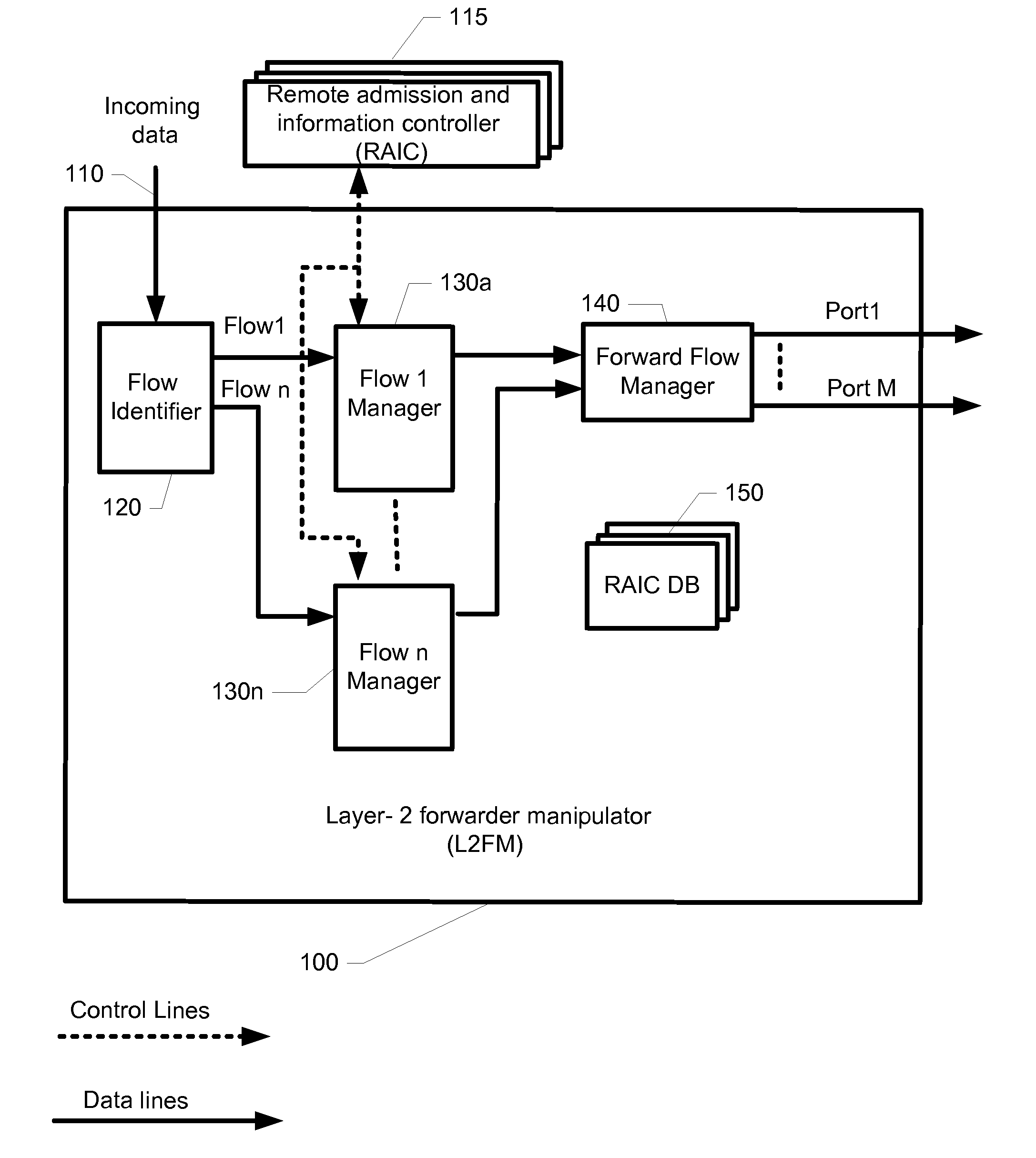
[0030]FIG. 1 depicts a block diagram with relevant elements of an exemplary Layer-2 Forwarder Manipulator 100 (L2FM), according to an exemplary embodiment of the present disclosure. Layer-2 Forwarder Manipulator 100 (L2FM) can comprise: a flow identifier 120, one or more flow managers 130a-n, a forward flow manager 140 and a RAIC database 150.

[0031]At initiation, all resources relevant to the L2FM 100 can be allocated, reset, and\or introduced to each other. Resources such as, but not limited to: forward flow manager 140, session flow manager 130a-n, and so on. L2FM 100 can be updated with different...


PUM


Abstract

The disclosure describes method and system for forwarding frames of a flow via a layer 2 forwarder and manipulator (L2FM) for improving network utilization and improving users experience by reducing the latency associated with the flow. When a new flow is identified, forward control information for frames of the new flow is obtained. The forward control information can include re-writing of at least one field in an original header of the frames of the new flow. At least one field in an original header of the frames of the new flow is manipulated according to the obtained forward control information, and the manipulated frames of the new flow are forwarded accordingly.

Description

CROSS-REFERENCE TO RELATED APPLICATIONS[0001]This application is a non-provisional application being filed under 35 USC 111 and 37 CFR 1.53(b) and claiming the benefit under 35 USC 119(e) of the U.S. Provisional Application for Patent that was filed on Sep. 9, 2009 and assigned Ser. No. 61 / 240,855, which application is hereby incorporated by reference.BACKGROUND[0002]The present disclosure relates generally to data communication over a plurality of networks that comply with the Open System Interconnection (OSI) model. More particularly the disclosure relates to optimizing communication paths between a source and destination of a flow.[0003]In networks, data is typically exchanged between communicating devices in the form of frames. A frame is a digital data transmission unit on the layer 2 of the Open System Interconnection (OSI) reference model, for example. It is used for data exchange between two points via a direct physical or logical link. The frame can include information on t...

Claims


Application Information

Patent Timeline
IPC IPC(8): H04L12/56
CPCH04L47/31H04L47/2483
Inventor HAREL, AMIRLELCUK, ALONNOSSENSON, RONITZAKAI, AVINOAM
Owner EXAFER
Why Eureka
Try Eureka