Device for spatially resolved temperature measurement

a technology of spatial resolution and temperature measurement, applied in the direction of measuring devices, thermometers, instruments, etc., can solve the problems of limiting the temperature resolution of dts devices, changing the polarization along the fiber, and affecting the polarization effect of dts measurements, so as to reduce the polarization dependence of thin-film filters and achieve sufficient polarization effects. small

Active Publication Date: 2011-03-10
NKT PHOTONICS GMBH
View PDF20 Cites 7 Cited by
  • Summary
  • Abstract
  • Description
  • Claims
  • Application Information

AI Technical Summary

Benefits of technology

[0031]One approach for reducing the polarization dependence of thin-film filters is the use of special layer designs which have very similar properties at the respective wavelength for both polarization components.
[0032]Another approach is the use of small angles of incidence. The filters are polarization-independent for normal incidence. At small angles of incidence, for example less than 10°, polarization effects can be sufficiently small so as to allow precise temperature measurements with an apparatus according to the invention.

Problems solved by technology

This is disadvantageous for the measurement time, but may have cost advantages as well as advantages for the accuracy, because identical channels are used for both signals.
One problem with spatially resolved temperature measurements using optical fibers is the change of the polarization along the fiber.
The problem associated with polarization effects in DTS measurements hence exists predominantly in single mode fibers and in measurements with multimode fibers having few modes or short lengths.
Even if the polarization effects affect the measured quantities only slightly, they can still have a significant effect on the determination of the temperature, possibly reaching, for example, several ° C. Such effects can therefore limit the temperature resolution of DTS devices.

Method used


Image

  • Device for spatially resolved temperature measurement
  • Device for spatially resolved temperature measurement
  • Device for spatially resolved temperature measurement

Examples


Embodiment Construction

[0038]Identical elements or elements performing the same function are indicated in the figures with identical references symbols.

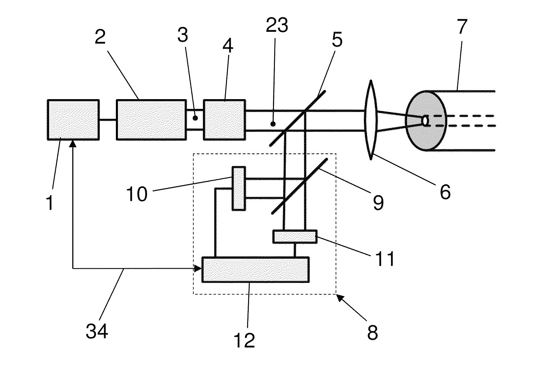
[0039]FIG. 1 illustrates an embodiment of an apparatus according to the invention with a laser light source 2 controlled by control means 1. The light 3 from the laser light source 2 passes through a polarization modifier 4 which can depolarize the light 3 or temporally and / or spatially change the polarization state of the light 3. After passing through the polarization modifier 4, the light 3 is coupled by coupling means, which include a spectral splitter 5 and for example a lens 6, into an optical fiber 7 used for the temperature measurement.

[0040]The lens 6 and the spectral splitter 5 also operate as decoupling means and can transmit the backscattered portions of the light 3 generated by the laser light source 2 to schematically indicated evaluation means 8. The evaluation means 8 include, for example, a spectral splitter 9 for the laser wavelength and ...


PUM

PropertyMeasurementUnit
angleaaaaaaaaaa
angleaaaaaaaaaa
angle of incidenceaaaaaaaaaa

Abstract

Apparatus for a spatially resolved temperature measurement, with at least one optical fiber (6) for the spatially resolved temperature measurement, and at least one laser light source (2) producing light (3, 23) which can be coupled into the optical fiber (6), wherein the portions of the light (3, 23) backscattered in the optical fiber (6) can be coupled out of the optical fiber (6) and evaluated. The apparatus further includes means for reducing polarization-induced effects, wherein the means may be, for example, a polarization modifier (4) capable of at least partially depolarizing the light (3).

Description

[0001]This is a continuation application of PCT / EP2009 / 001879, filed on Mar. 14, 2009, claiming priority to DE 10 2008 023 777.9 filed on May 15, 2008.BACKGROUND OF THE INVENTION[0002](1) Field of the Invention[0003]The present invention relates to an apparatus for spatially resolved temperature measurement according to the preamble of claim 1.[0004](2) Description of Related Art[0005]An apparatus of the aforedescribed type is disclosed, for example, in EP 0 692 705 A1. Fiber-optic temperature measurement systems (Distributed Temperature Sensing—DTS) can employ optical effects in optical fibers for spatially resolved temperature measurements. For example, the effect caused by Raman scattering can be used. The radiation from a narrowband source of electromagnetic radiation (e.g., from a laser) is inelastically scattered in the fiber material. The ratio of the intensities of the scattered radiation with a wavelength shorter than the excitation wavelength (anti-Stokes scattered radiati...

Claims


Application Information

Patent Timeline
Patent Type & Authority Applications(United States)
IPC IPC(8): G01K11/32
CPCG01K11/32
Inventor HILL, WIELAND
Owner NKT PHOTONICS GMBH
Why Eureka
Try Eureka