
Bonded assemblies and methods for improving bond strength of a joint

Inactive Publication Date: 2011-03-10
HONEYWELL INT INC
View PDF9 Cites 26 Cited by
  • Summary
  • Abstract
  • Description
  • Claims
  • Application Information

AI Technical Summary

Benefits of technology

[0006]The present invention provides strengthened bonded assemblies and methods for improving the bond strength of a joint. In one embodiment, and by way of example only, a method for improving the bond strength of a joint between bonding surfaces of a first and a second component is disclosed. A first component may be provided having a bonding surface adapted to be bonded to a bonding surface of a second component. A plurality of features is formed in at least one of the bonding surfaces. The plurality of features may project or recede from the bonding surface. A bonding material layer is applied between the bonding surfaces and into the receded plurality of features and / or around the plurality of features to form a chemical and mechanical bond improving the strength of the joint between the components.

Problems solved by technology

The problems which are inherent in forming a joint between dissimilar materials are well known to those skilled in the art.
In general, dissimilar materials, such as for example, a composite material and a metal material, often do not form good bonds with each other.
The joints formed may be unsatisfactory.
However, such leading edges are subject to often severe environmental conditions such as erosion and foreign object damage which can lead to premature failure of the bondline, undesirably causing the joined components to separate.
Current bonding techniques typically involve elaborate surface preparation, however, they do not always work well with material combinations across different joint types and may not be able to withstand various loading and environmental factors without incurring unnecessary weight and cost.
Moreover, the geometry of the components themselves may not provide adequate surface area to provide a good bond.

Method used


Image

  • Bonded assemblies and methods for improving bond strength of a joint
  • Bonded assemblies and methods for improving bond strength of a joint
  • Bonded assemblies and methods for improving bond strength of a joint

Examples


Embodiment Construction

[0025]The following detailed description of the invention is merely exemplary in nature and is not intended to limit the invention or the application and uses of the invention. Furthermore, there is no intention to be bound by any theory presented in the preceding background of the invention or the following detailed description of the invention.

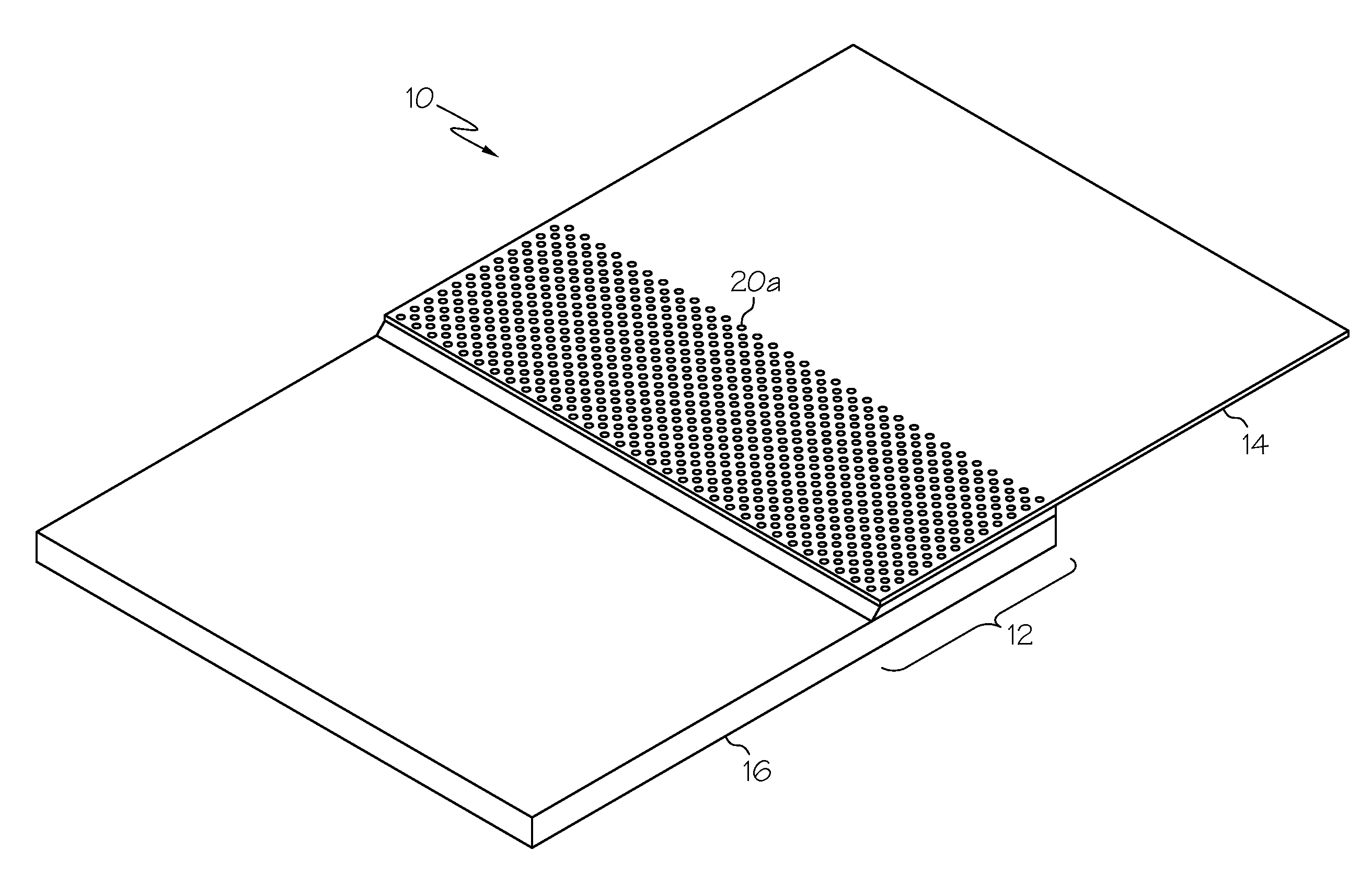
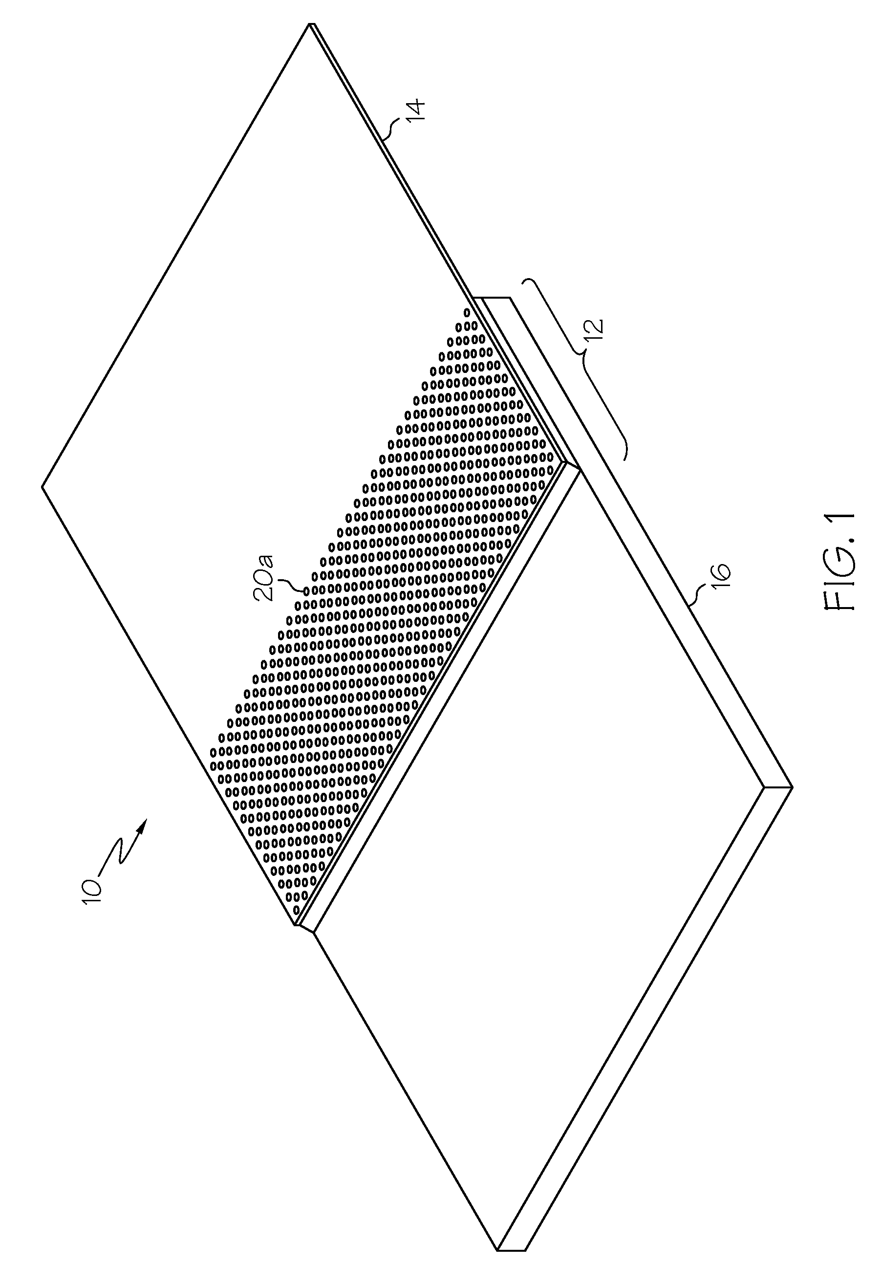
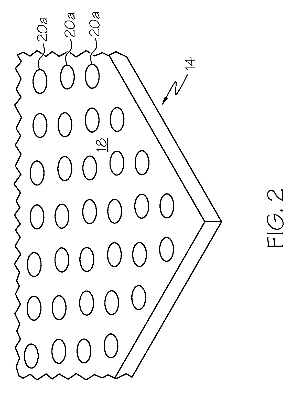
[0026]FIGS. 1-15 illustrate methods in accordance with exemplary embodiments of the present invention for improving the bond strength of a joint in a bonded assembly 10 between two or more components each having at least one bonding surface. Such embodiments include the formation of a plurality of features in a bonding surface of at least one of the components and bonding the respective bonding surfaces together with a bonding material or by co-curing the components.

[0027]Referring to FIGS. 1-5, in accordance with an exemplary embodiment of the present invention, a method for improving the bond strength of a joint 12 includes the step of pro...


PUM

PropertyMeasurementUnit
Thicknessaaaaaaaaaa
Areaaaaaaaaaaa
Mechanical propertiesaaaaaaaaaa

Abstract

Bonded assemblies and methods for improving the bond strength of a joint are provided. The joint may be formed between bonding surfaces of a first and a second component. The first component has a bonding surface adapted to be bonded to a bonding surface of a second component. A plurality of features may be formed in at least one of the bonding surfaces. The bonding surfaces are bonded together to form the joint. A bonding material layer between the bonding surfaces may form the joint or the first and second components may be co-cured to form the joint. A chemical and mechanical bond between the bonding surfaces is formed with the plurality of features forming the mechanical bond and increasing the bond area of the chemical bond. The features may be openings and / or protrusions such as holes, slots, and bosses.

Description

TECHNICAL FIELD[0001]The present invention relates to bonded assemblies and methods for joint formation, and more particularly, to strengthened bonded assemblies and methods for improving bond strength in a joint.BACKGROUND[0002]There are many applications and systems which involve the bonding of two or more components made of similar or dissimilar materials. The problems which are inherent in forming a joint between dissimilar materials are well known to those skilled in the art. In general, dissimilar materials, such as for example, a composite material and a metal material, often do not form good bonds with each other. The joints formed may be unsatisfactory. For example, in high performance products, a metallic material may be bonded to the surface of a composite. Composite materials have gained popularity in high-performance products that need to be lightweight, yet strong enough to withstand harsh loading and environmental conditions. Such high-performance products include aer...

Claims


Application Information

Patent Timeline
IPC IPC(8): B32B3/06B32B37/14
CPCB23K1/0018Y10T428/24008B23K28/02B23K2201/001B29C65/5057B29C66/1122B29C66/301B29C66/30321B29C66/30325B29C66/43B29C66/474B29C66/721B29C66/742B29C66/7461B29L2031/082B29L2031/085B29L2031/3076C09J5/00F01D5/282F16B11/006Y02T50/672C09J2400/163B29C65/483B23K1/20B29C66/71B23K2101/001F04D29/324F05D2240/303Y02T50/60Y02P70/50B29K2063/00
Inventor GAGE, RAYMONDALLAN, ADRIAN
Owner HONEYWELL INT INC
Learn More