Cooling system and battery cooling system

Inactive Publication Date: 2011-03-10
SAMSUNG ELECTRONICS CO LTD
View PDF64 Cites 44 Cited by
  • Summary
  • Abstract
  • Description
  • Claims
  • Application Information

AI Technical Summary

Benefits of technology

[0006]Aspects of the present invention include a cooling system and a battery cooling system that incl

Problems solved by technology

A battery or fuel cell used in a high-output device, such as an automobile or the like, may overheat due to having high heating value.
It may be inadequate to cool a heated me

Method used


Image

  • Cooling system and battery cooling system
  • Cooling system and battery cooling system
  • Cooling system and battery cooling system

Examples


Embodiment Construction

[0030]Reference will now be made in detail to the present embodiments of the present invention, examples of which are illustrated in the accompanying drawings, wherein like reference numerals refer to the like elements throughout. The embodiments are described below in order to explain the present invention by referring to the figures.

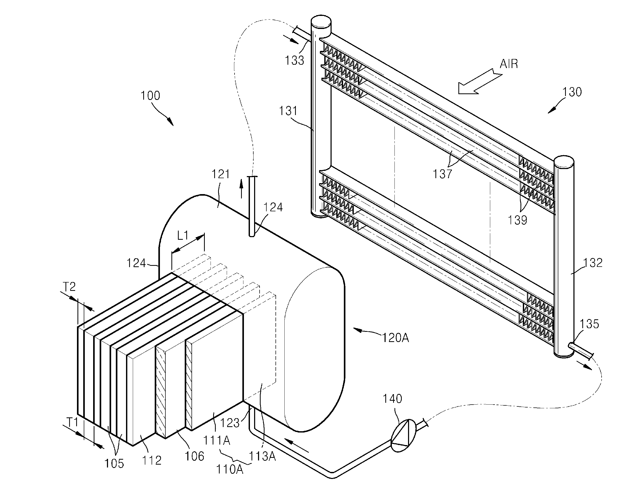
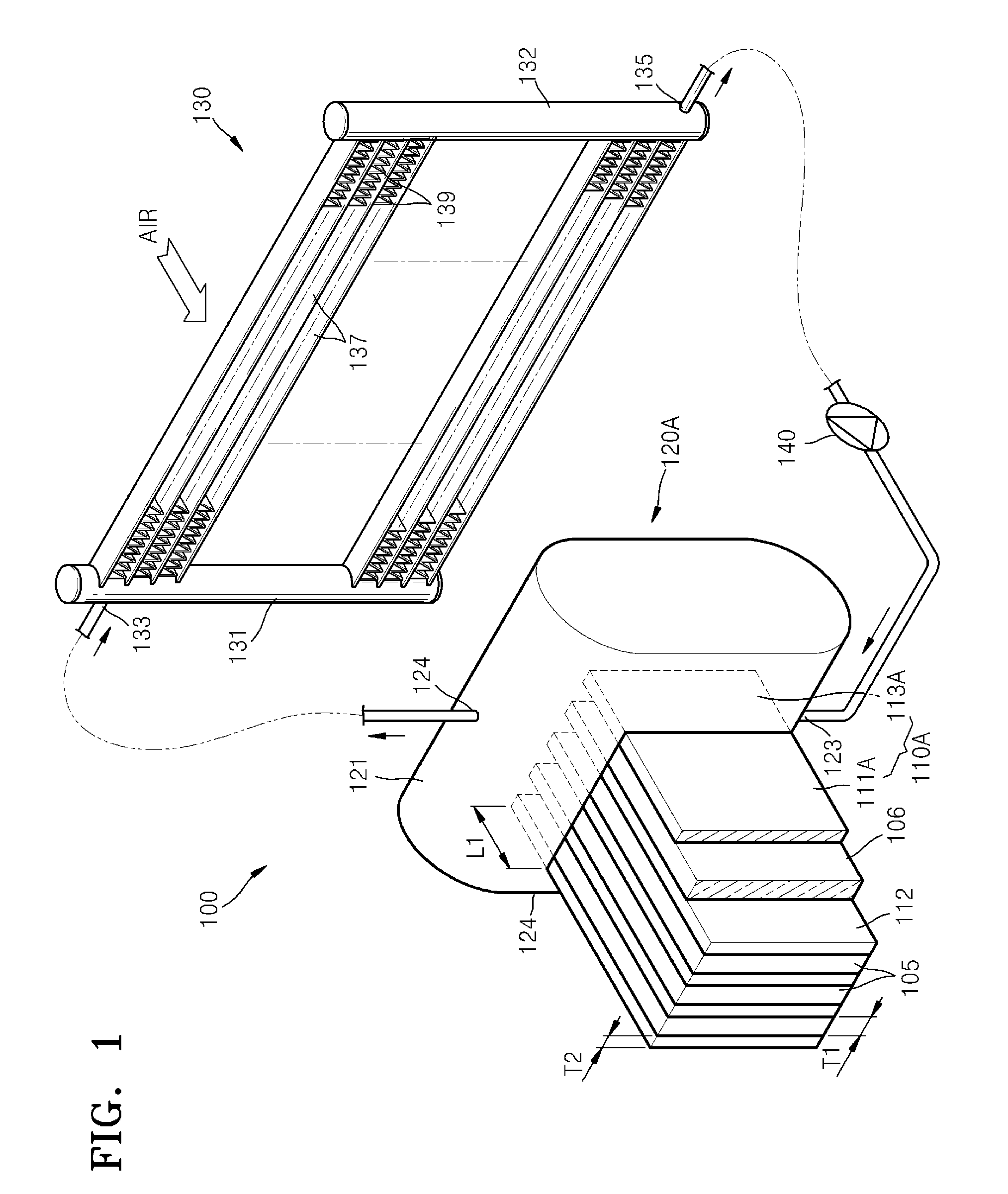
[0031]FIG. 1 is a diagram of a heated member cooling system 100 according to an embodiment of the present invention. The heated member cooling system 100 includes a plurality of heated members 105, a plurality of heat pipes 110A, a first heat exchange unit 120A, and a second heat exchange unit 130. The heated member cooling system 100 is a system in which a refrigerant circulates through the first heat exchange unit 120A and the second heat exchange unit 130; absorbs heat from the heated members 105 in the first heat exchange unit 120A in such a manner that the refrigerant, in a liquid state, is partly vaporized; and emits the heat to air in the second...


PUM


Abstract

A cooling system includes a heat pipe for contacting a heated member and absorbing heat from the heated member, and a first heat exchange unit for containing a refrigerant that is heated by absorbing the heat from a heat emitting part. Also, the heated member cooling system includes a second heat exchange unit for containing the refrigerant entered from the first heat exchange unit and cooling the refrigerant, and for emitting the cooled refrigerant to the first heat exchange unit.

Description

CROSS-REFERENCE TO RELATED APPLICATION[0001]This application claims the benefit of Korean Application No. 10-2009-0083985, filed in the Korean Intellectual Property Office on Sep. 7, 2009, the disclosure of which is incorporated herein by reference.BACKGROUND[0002]1. Field[0003]The present disclosure relates to a heated member cooling system for prevention of overheating of a heated member including a battery cell, a fuel cell, a semiconductor chip or the like.[0004]2. Description of the Related Art[0005]A battery or fuel cell used in a high-output device, such as an automobile or the like, may overheat due to having high heating value. In such circumstances, it may be necessary to supply the battery or fuel cell with a cooling device to prevent overheating. It may be inadequate to cool a heated member having a high heating value using a cooling device of an air cooling type, and mainly, the heated member may be cooled by using a cooling device of a liquid cooling type. Thus, it is ...

Claims


Application Information

Patent Timeline
IPC IPC(8): H01M10/50F25B30/00F25D17/02F28D15/02F28D21/00
CPCF28D15/0233Y02E60/50F28D15/0275H01M8/04007H01M8/04074H01M10/5004H01M10/5016H01M10/5032H01M10/5046H01M10/5048H01M10/5057H01M10/5059H01M10/5073H01M10/5075H01M10/5079F28D15/0266H01M10/613H01M10/625H01M10/647H01M10/6551H01M10/6552H01M10/6556H01M10/6557H01M10/6566H01M10/6567H01M10/6569Y02E60/10H01M10/6568
Inventor JEONG, JI-YOUNGKIM, DONG-KWANPAIK, MEEN-SEONPARK, TAE-SANG
Owner SAMSUNG ELECTRONICS CO LTD
Why Eureka
Try Eureka