

Automated particulate concentration system
a technology of automatic concentration and particulate, which is applied in the direction of chemiluminescene/bioluminescence, material analysis by resonance, after-treatment of biomass, etc., can solve the problems of increasing the complexity of the concentration process, requiring manual control of the system, and none of the automatic control is amenabl
- Summary
- Abstract
- Description
- Claims
- Application Information
AI Technical Summary
Benefits of technology
Problems solved by technology
Method used
Image

Examples
example 1
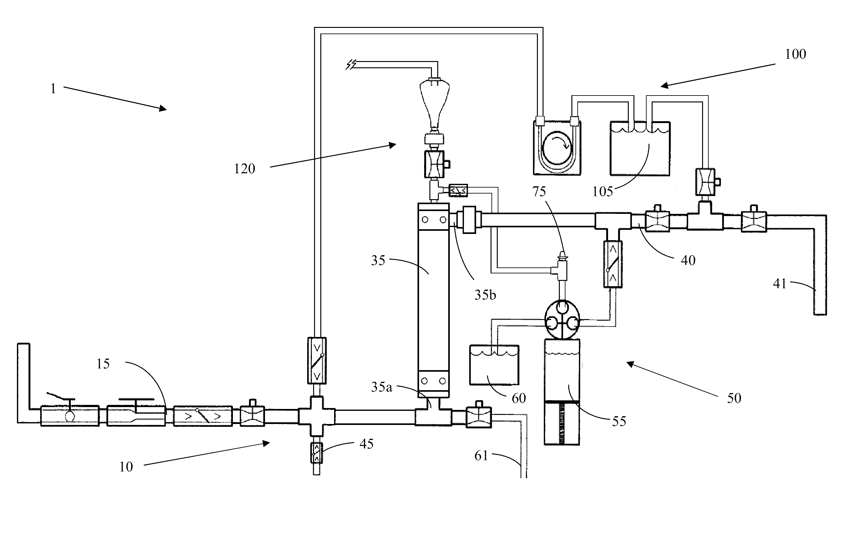
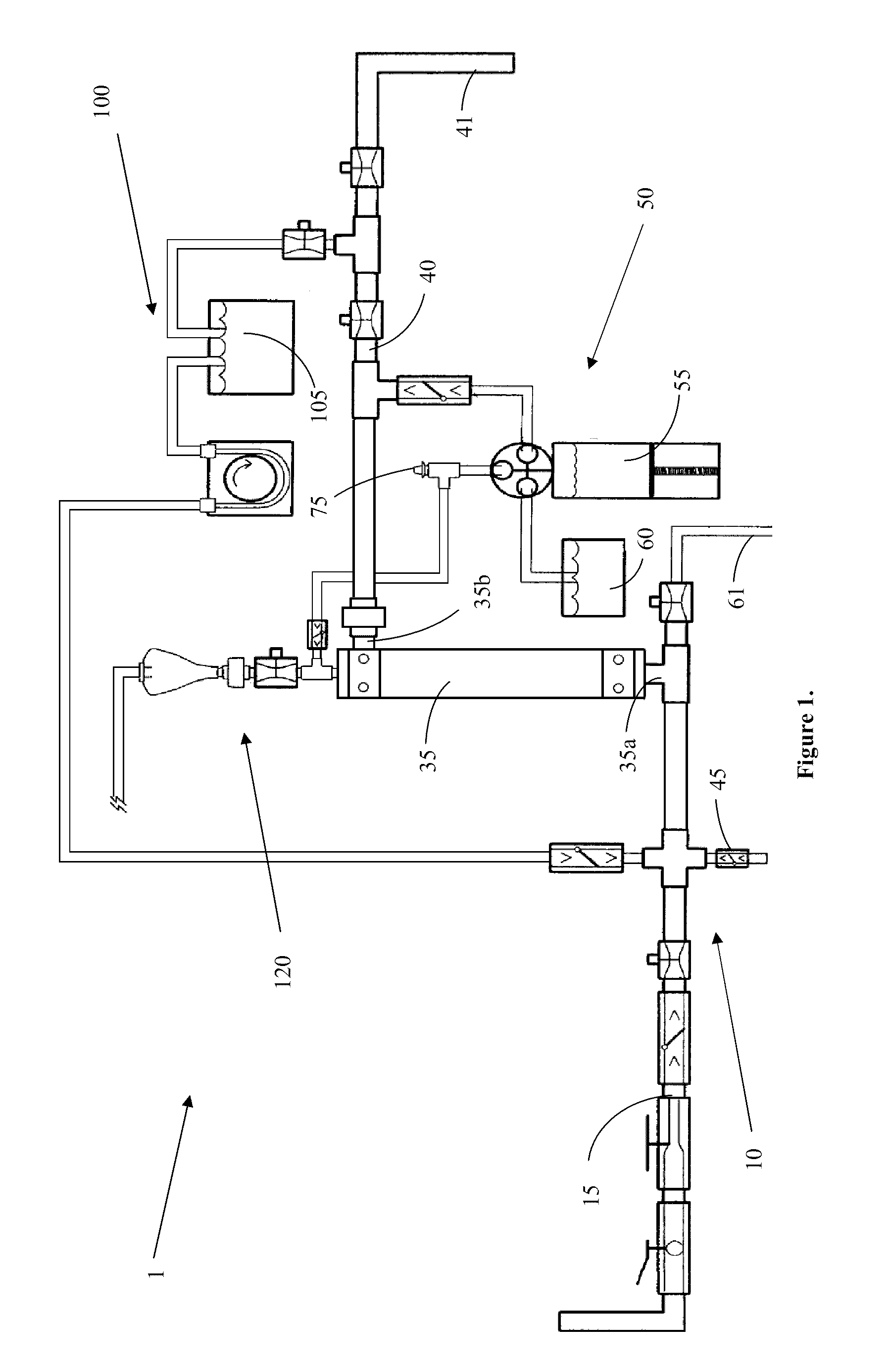
[0050]Referring now to the figures, FIG. 1 shows a schematic view of an illustrative device. Automated Concentration System (ACS) 1 comprises forward-flow concentration subsystem 10, with a backflush compatible filter, backflush subsystem 50, cleaning subsystem 100 and purge subsystem 120. The filter in the present example is a tubular hollow fiber filter having an interior, such as a core, and an exterior outside of the fiber walls or housing side.
Forward-Flow Concentration Subsystem (FFC)
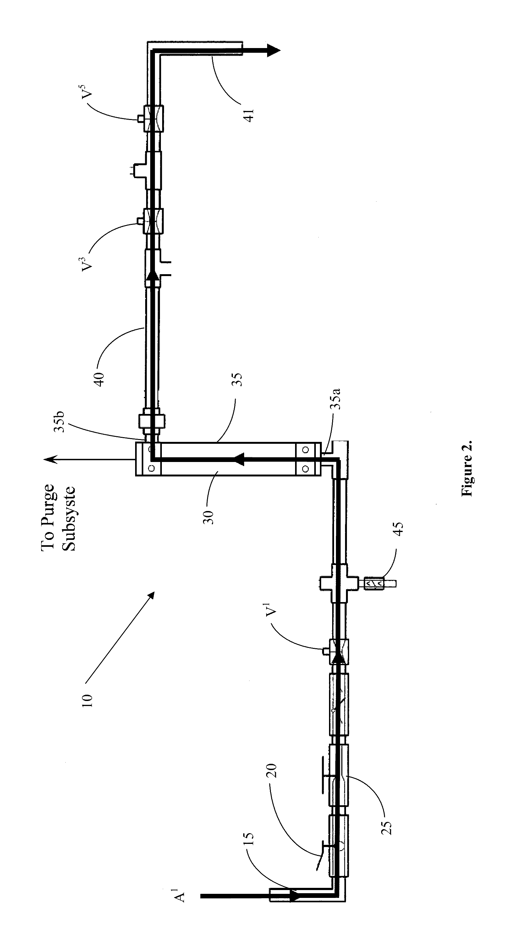
[0051]Forward-flow concentration subsystem (FFC) 10, shown in FIG. 2, includes filter housing 35, with a fluid input 35a and a fluid output 35b. Filter housing 35 contains a filter 30 comprised of hollow, tubular fibers. Fluid input 35a is disposed toward the center of filter housing 35, to permit test fluid to flow into the interior of the fibers of filter 30. Fluid input 35a is attached to source line 15, thereby directing the test fluid flow from a fluid source through FFC 10 as indicated by ar...
example ii
[0065]In addition to the concentrator in Example I, another embodiment of the concentrator, shown in FIG. 6, may include the capability to forward flow the recovery fluid, i.e. flow the recovery fluid in the same path of travel as test fluid, as seen in FIG. 7. Forward flow buffer line 57 is in fluid communication with source line 15, allowing the recovery fluid to enter filter housing 35 through fluid input 35a, leading into the fiber cores of filter 30. Mass control valve V7 controls the introduction of recovery fluid into source line 15, which permits the system to equilibrate filter 30 to the recovery fluid before the backflush sequence begins. In some embodiments, the recovery fluid is obtained from solution reservoir 60 using backflush pump 55. In this embodiment, liquid / air forward flow line 57 is in fluid communication with the output end of backflush pump 55 and forward flow buffer line 56 takes up buffer from solution reservoir 60 via backflush pump 55. Uptake of recovery ...
example iii
Concentration of E. coli O157:H7 Spiked into Tap Water
[0068]A new 0.8 mm Norit hollow fiber filter or a used filter that had been soaking in 1% bisulfite solution preservative was used for each test. The filter was installed in the concentration system, the input line connected to a faucet and the filter rinsed with tap water to remove storage solution. The filter was then backflushed with distilled water. Prior to spiking, water was run through the filter in the forward direction for 5-7 minutes and the pressure before and after the filter and flow rate were measured. When a previously used and cleaned filter was used in a test, blank water samples were collected and recovered before each test and after each test to confirm that no residual test organisms carried over between experiments.
[0069]For each test, E. coli O157:H7 cells labeled with green fluorescent protein (GFP) were diluted into a syringe with 10 ml of distilled water and spiked into the tap water flowing into the conc...
PUM
| Property | Measurement | Unit |
|---|---|---|
| Volume | aaaaa | aaaaa |
| Volume | aaaaa | aaaaa |
| Volume | aaaaa | aaaaa |
Abstract
Description
Claims
Application Information