
Group signature system, apparatus and storage medium

a group signature and storage medium technology, applied in the field of group signature systems, apparatus and storage media, can solve the problems of poor practical efficiency and poor system efficiency of a group including a large number of members, and achieve the effect of improving the calculation speed

Active Publication Date: 2011-03-10
TOSHIBA DIGITAL SOLUTIONS CORP +1
View PDF10 Cites 34 Cited by
  • Summary
  • Abstract
  • Description
  • Claims
  • Application Information

AI Technical Summary

Benefits of technology

[0017]According to the investigation of the present inventor, there is room for decreasing a calculation amount to improve a calculation speed while providing a revocation function as compared with [CG04], [F105] and [DP06] systems.
[0018]An object of the present invention is to provide a group signature system, an apparatus and a storage medium which can decrease a calculation amount to improve a calculation speed while realizing a revocation function.
[0020]According to the first aspect, there is provided the group signature system based on a complete discrete logarithm in which the multiplication cyclic group gG of prime order q is used. Moreover, the group signature system is realized so that the representation parts ki1 and ki2 constitute the member private key and so that the part ki1 of the representation of the revoked member is included in the revocation list. In consequence, as compared with conventional [CG04], [FI05] and [DP06] systems, a calculation amount can be decreased to increase a calculation speed. Further, in the group signature of the present invention, the group administrator function can be divided by the member private key generator, the signer tracer and the revocation administrator, whereby weak non-frameability obtained by slightly weakening conventional non-frameability and self-traceability can simultaneously be realized.

Problems solved by technology

Therefore, the system has a very poor efficiency for a group including a large number of members, and is thus not suitable for a realization.
However, in the system of Camenisch et al., the efficiency does not depend on the number of the members, but the efficiency is poor from a practical viewpoint.

Method used


Image

  • Group signature system, apparatus and storage medium
  • Group signature system, apparatus and storage medium
  • Group signature system, apparatus and storage medium

Examples


first embodiment

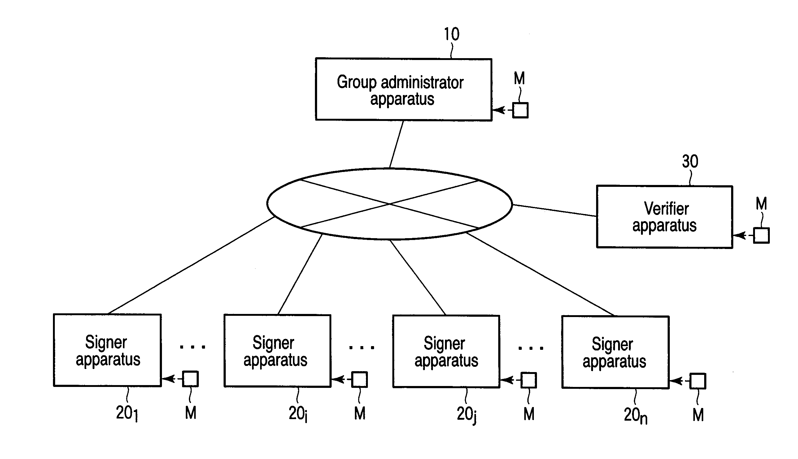
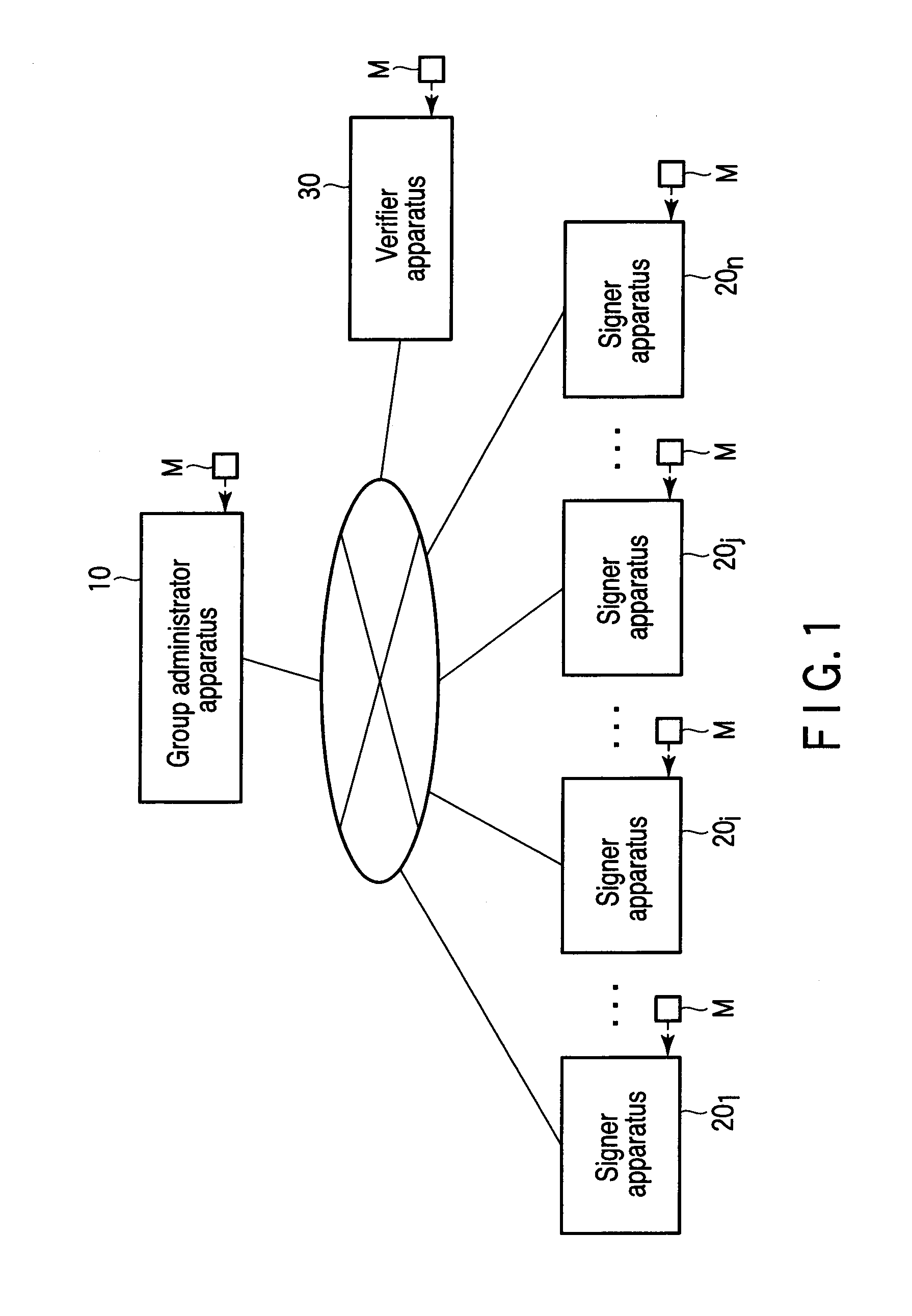
[0141]FIG. 1 is an exemplary diagram showing a constitution of a group signature system according to one embodiment of the present invention. This group signature system comprises one group administrator apparatus 10, n signer apparatuses 201, . . . , 20i, . . . , 20j, . . . and 20n and one verifier apparatus 30 so that the apparatuses can communicate with one another. For each of the apparatuses 10, 201, . . . , 20n and 30, a hardware constitution or a combined constitution of a hardware resource and software can be carried out. As the software of the combined constitution, a program is used which is beforehand installed from a network or storage medium M to a computer of the corresponding apparatus to realize the function of the corresponding apparatus. Moreover, the signer apparatuses 201, . . . and 20n have the same hardware constitution, and hence in the description, the i-th signer apparatus 20i will representatively be described. Moreover, in the group signature system of the...

second embodiment

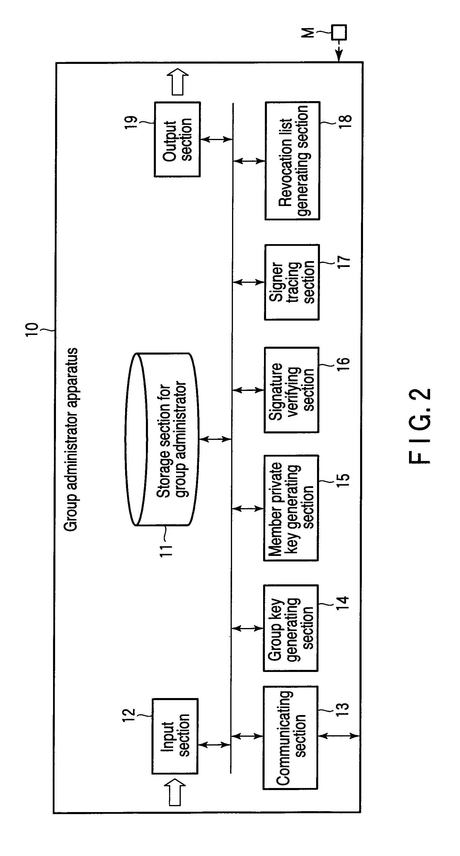
[0310]FIGS. 22 and 23 are exemplary diagrams showing constitutions of a member private key generator apparatus and a storage section of the apparatus according to a second embodiment of the present invention. FIGS. 24 and 25 are exemplary diagrams showing constitutions of a signer tracing apparatus and a storage section of the apparatus. FIGS. 26 and 27 are exemplary diagrams showing constitutions of a representation administrator apparatus and a storage section of the apparatus. In FIGS. 22 to 27, the same function as the above function is denoted with the same reference numerals as those of the above diagrams, detailed description thereof is omitted, and a different part will mainly be described here. It is to be noted that in the following embodiment, redundant description is similarly omitted.

[0311]First, the group administrator apparatus 10 of the first embodiment has a plurality of different functions of the group key generating section 14, the member private key generating se...

third embodiment

[0335]FIGS. 28 and 29 are exemplary diagrams showing constitutions of a signer identity proving apparatus and a storage section of the apparatus according to a third embodiment of the present invention.

[0336]First, as shown in FIG. 4, the signer apparatus 20i in the first embodiment has a plurality of different functions of the message preparing section 24, the group signature generating section 25 and the signer identity proving section 26 in addition to the input section 22, the output section 27 and the communicating section 23 having universally utilized functions. On the other hand, as shown in FIGS. 28 and 29, the third embodiment has a constitution in which a signer identity proving apparatus 201i is extracted from the signer apparatus 20i shown in FIG. 4.

[0337]As shown in FIG. 28, the signer identity proving apparatus 201i comprises a signer identity proving confidential information storage section 211, a communicating section 23 and a signer identity proving section 26. Add...


PUM


Abstract

A group signature system according to one embodiment of the present invention comprises a group administrator apparatus, signer apparatuses and a verifier apparatus which can communicate with one another. Here, in a group signature method used by the apparatuses, a multiplication cyclic group or a bilinear group in which an order is unknown as in RSA is not used at all, but a multiplication cyclic group gG of a prime order q is only used, and representation parts ki1 and ki2 are used as a member private key. Moreover, as information for tracing a signer, Ti=G1̂{ki1} is utilized, and ki1 is utilized for verifying revocation. In consequence, a calculation amount can be decreased to increase a calculation speed as compared with conventional [CG04], [FI05] and [DP06] systems.

Description

CROSS REFERENCE TO RELATED APPLICATIONS[0001]This is a Continuation Application of PCT Application No. PCT / JP2009 / 054502, filed Mar. 10, 2009, which was published under PCT Article 21(2) in Japanese.[0002]This application is based upon and claims the benefit of priority from prior Japanese Patent Application No. 2008-072488, filed Mar. 19, 2008, the entire contents of which are incorporated herein by reference.BACKGROUND OF THE INVENTION[0003]1. Field of the Invention[0004]The present invention relates to a group signature system, an apparatus and a storage medium, and more particularly, it relates to a group signature system, an apparatus and a storage medium which can decrease a calculation amount to improve a calculation speed.[0005]2. Description of the Related Art[0006]A group signature system in which electronic signatures have anonymity was suggested by Chaum et al. in 1991. In a usual electronic signature system, a public key for verifying a signature corresponds to a privat...

Claims


Application Information

Patent Timeline
IPC IPC(8): H04L9/32
CPCH04L9/302H04L9/3073H04L9/3218H04L2209/42H04L9/3255
Inventor YOSHIDA, TAKUYAOKADA, KOJI
Owner TOSHIBA DIGITAL SOLUTIONS CORP
Learn More