Exhaust purification device of internal combustion engine

a technology of purification device and internal combustion engine, which is applied in the direction of electrical control, exhaust treatment electric control, separation process, etc., can solve the problem of difficult to get all of the fed aqueous urea solution to be adsorption in the form of ammonia

Active Publication Date: 2011-03-17
TOYOTA JIDOSHA KK
View PDF6 Cites 26 Cited by
  • Summary
  • Abstract
  • Description
  • Claims
  • Application Information

AI Technical Summary

Benefits of technology

[0008]That is, at the time the engine is stopped, the temperature of the exhaust system as a whole is high, so a sufficient amount of ammonia can b

Problems solved by technology

Therefore, when a NOX selective reduction catalyst is used, usually, when there is a request to start the engine, the engine is immediately started and the temperature of the NOX selective reduction catalyst is caused to rise by the exhaust gas exhausted from the engine.
However, right after engine start, the temperature at the wall surfaces inside the exhaust passage is low, so the fed aqueous urea solution continues to stick on the wa

Method used


Image

  • Exhaust purification device of internal combustion engine
  • Exhaust purification device of internal combustion engine
  • Exhaust purification device of internal combustion engine

Examples


first embodiment

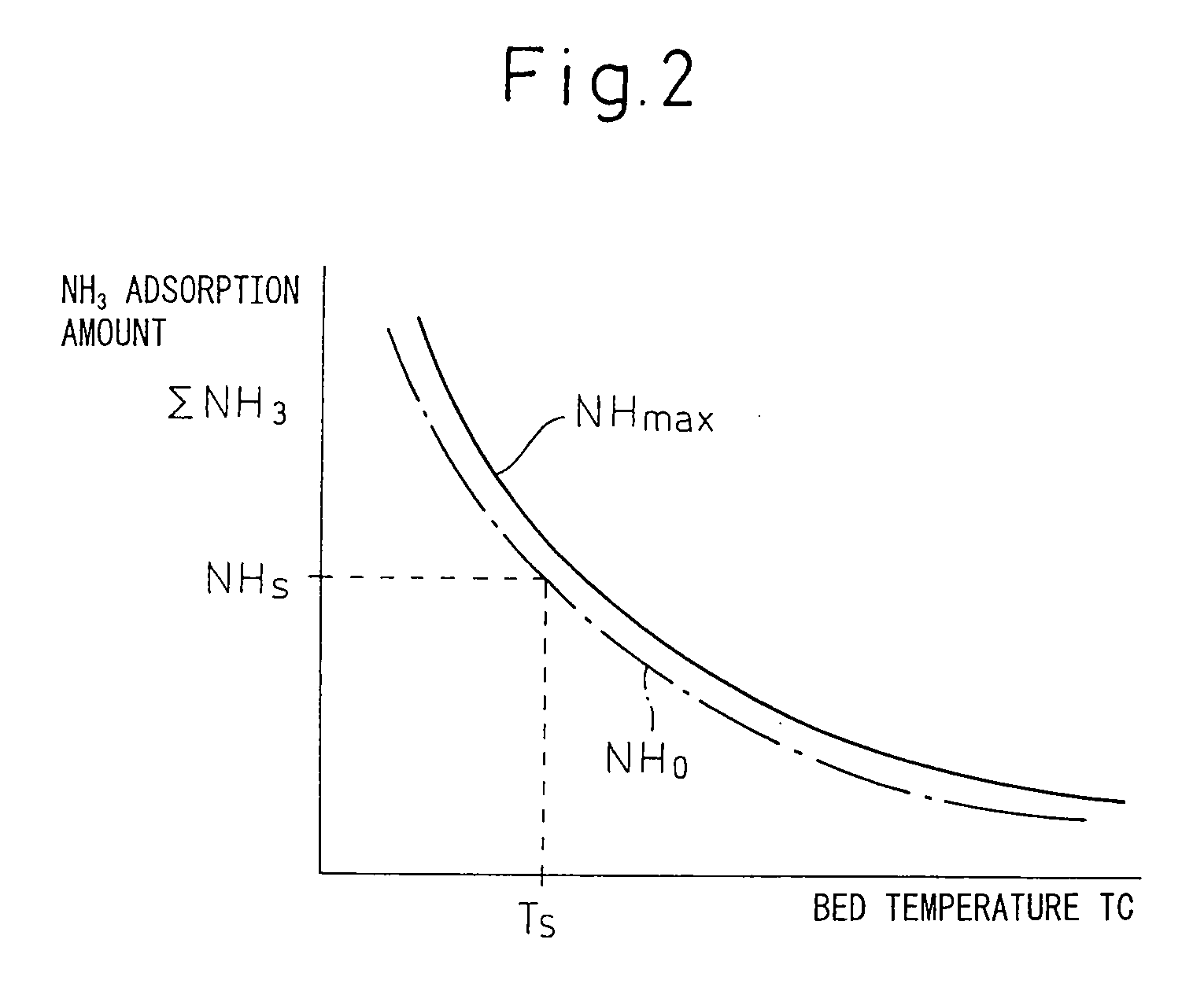
[0037]Therefore, in the present invention, when an operation for stopping the engine is performed, if the ammonia adsorption amount ΣNH3 at the NOX selective reduction catalyst 15 is smaller than the target amount of adsorption NHS at the time the engine is stopped, the engine operation is continued to lower the temperature TC of the NOX selective reduction catalyst 15, the urea necessary for making the ammonia adsorption amount ΣNH3 at the NOX selective reduction catalyst 15 the target amount of adsorption NHS at the time the engine is stopped is fed to the NOX selective reduction catalyst 15, then the engine is stopped. Note that, “when an operation for stopping the engine is performed” are includes, for example, when an instruction for stopping the engine is given in a hybrid engine where the engine is driven in accordance with need.

[0038]FIG. 5 shows the control routine of the ammonia adsorption amount at the time the engine is stopped for working this first embodiment.

[0039]Ref...

second embodiment

[0042]FIG. 7 shows the control routine of the ammonia adsorption amount at the time the engine is stopped for working this

[0043]Referring to FIG. 7, first, at step 70, it is determined if the ignition switch 43 has been switched from on to off, that is, whether an operation to stop the engine has been performed. When the ignition switch 43 is switched from on to off, that is, when an operation to stop the engine has been performed, the routine proceeds to step 71 where it is determined if the ammonia adsorption amount ΣNH3 is larger than the target amount of adsorption NHS of ammonia at the time the engine is stopped. Note that, in this case as well, as the ammonia adsorption amount ΣNH3, the ammonia adsorption amount ΣNH3 calculated at step 53 of FIG. 3 is used.

[0044]When it is determined at step 71 that ΣNH3≧NHS, the routine proceeds to step 74 where the engine is stopped. As opposed to this, when it is determined at step 71 that ΣNH3S, that is, when the ammonia adsorption amount ...


PUM

PropertyMeasurementUnit
Temperatureaaaaaaaaaa
Adsorption entropyaaaaaaaaaa

Abstract

In an internal combustion engine, an NOX selective reduction catalyst (15) is arranged in an engine exhaust passage, an aqueous urea solution is fed to the NOX selective reduction catalyst (15) and the ammonia generated from the aqueous urea solution is made to be adsorbed at the NOX selective reduction catalyst (15), and the adsorbed ammonia is used to selectively reduce NOX. At the time the engine is stopped, when the ammonia adsorption amount at the NOX selective reduction catalyst (15) is smaller than a predetermined target amount of adsorption, the urea necessary for making the ammonia adsorption amount at the NOX selective reduction catalyst (15) the target amount of adsorption is fed to the NOX selective reduction catalyst (15) at the time the engine is stopped.

Description

TECHNICAL FIELD[0001]The present invention relates to an exhaust purification device of an internal combustion engine.BACKGROUND ART[0002]Known in the art is an internal combustion engine arranging a denitration catalyst in an engine exhaust passage, feeding air containing ammonia upstream of the denitration catalyst to make ammonia be adsorbed at the denitration catalyst, and using the adsorbed ammonia to reduce the NOX in the exhaust gas (for example, see Japanese Patent Publication (A) No. 2006-257936). In this internal combustion engine, to make the NOX reduction action by the denitration catalyst start right after engine startup, when the engine should be started, before starting the engine, the denitration catalyst is preheated and, after the denitration catalyst is activated, the engine is started.[0003]In this regard, in the past, an NOX selective reduction catalyst comprised of for example Fe zeolite was used for reducing NOX in the presence of ammonia. In this case, usuall...

Claims


Application Information

Patent Timeline
IPC IPC(8): F01N9/00F01N3/10
CPCB01D53/9431B01D53/9495B01D2251/2067F01N3/208Y02T10/24F01N2610/02F01N2900/1622F02D41/0235F02D41/042F01N2570/14Y02A50/20Y02T10/12
Inventor AOYAMA, TAROTANAI, YUTAKA
Owner TOYOTA JIDOSHA KK
Why Eureka
Try Eureka